Arduino based racing car problems

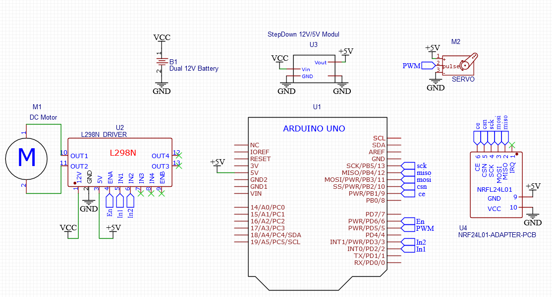
So I am designing and developing an Arduino-based racing car equipped with a robust suspension system, gears for efficient power transmission and stability, and a NRF module for remote control and telemetry. But for the schematic diagram of the circuits for the car i am confused of where to use resistors and capacitors of what values and also my circuit is correct or not please help...

components I use are :
arduino uno r3
servo OT90MR
2 lithium ion polymer batteries>11.1V2200mAh3C
L298N Module
Nrf24L01 module
RS550 DC motor

can someone help with circuits i will be highly grateful
thank you

regards.

5V regulator of arduino may have not enough current vor powering servo.
3V voltage regulator of arduino have not enough current to power NRF module.

you mean "DC motor", RS550 is a simple DC motor.

Umm sorry I am using 2 motors one is servo and also DC motor forgot to write also using voltage regulator 5V for the NRF and DC motor operates voltage 6-12V

show

Yeah I will edit it thank you but is the schematic is correct except that 5V voltage (I will add it up)

Thanks for the diagram but about the capacitor and resistors?

on the diagram are only module, each module contains needed components.

Most modules use 3.3V.
Are you sure your module can use 5V?

It's 1.9V - 3.3V

Like for example I don't get it

Then why are you using 5V??

only maybe will 10µF capacitor needed, directly on 3v/GND of nRF24L01 module, bc on the adapter it is maybe too small

Sorry it got autocorrected

Okay that's it only 10 microfarad capacitor needed? If this is it thank you so much!!!

What got autocorrected?
You will burn out the NRF24L01

import in EasyEda
SCH_New-Project_2024-07-08.json (27.9 KB)

its not opening

Hi. @ibunny30
Welcome to the forum.

Rather than a screen capture, you can EXPORT a png image.
Look under the File tab, it will produce a good resolution image without the menu and other screen items.

Tom.. :smiley: :+1: :coffee: :australia: