At home you can work with the WOKWI-simulator
You can work especcially on the code-logic that does not require real hardware.
Anyway the WOKWI-simulator offers quite some hardware to simulate too
best regards Stefan
At home you can work with the WOKWI-simulator
You can work especcially on the code-logic that does not require real hardware.
Anyway the WOKWI-simulator offers quite some hardware to simulate too
best regards Stefan
We don't know how to use them. We can't understand how the program recognizes that if we place a Dupont cable there it knows that it is a pin 3 for example. I think that I explained myself really badly, you tell me.
I was using the online version but I just installed the 1.8.19 version. We will try that tomorrow.
The operating system? I don't know how to look at that. It looks like this, idk if this can help.

It could be C++, but I don't have any idea.
What operating system is the computer you're using to program with? Windows, Mac, Chrome, etc.?
what is your mother-language? your native language?
Okay, so you are meaning like my computer system? I have a Lenovo, installed with Windows.
Now I have tried the program I the 1.8 and it works a bit, at least it turns on. However, there are three main problems.


Thanks for your help!
-jj
If the connections are good enough (i.e. no cold soldering, no lossy cables, etc.), from the code point of view there's no difference on how the connections are made, even if you have soldered together three cables without any support like a connector or soldered to the board using that free holes. What I'm trying to say you (as an advise for a better workout) is to begin some more consistent cabling and assembling.
No, the motors are two, A and B. Since they need two wires to power them, as you can see coming out of the motors, you have a total of 4 wires, motor right 1 and 2, and motor left 1 and 2, connected to that 4 screws.
But, please,please look at the (very) similar project I linked you twice before, you'll be able to better and quicker understand some basics I suspect you need to know and properly manage:
The link is this:
https://projecthub.arduino.cc/lightthedreams/34b1d3f5-b31e-46fe-b57a-156fbf440cc1
I don't know how exactly you made your cabling. The picture you sent now shows only ONE motor connected, to pins 1 and 2 of motor A. Where are the wires for motor B?
As the motors are controlled via the sensors, there's a logic chain to be checked. The problem could be anything from this list:
To be able to identify the problem you need some checks. For instance, if you doublt a motor could be defective, just connect it to a battery (use a suitable voltage for that motor, like 6V or 9V): if it goes, you can exclude the first point, so you can go on with the next steps.
But do the tests with the code from the above example project, just to start excluding programming issues, and tell us the result of your checks.
PS: when the hardware is ok, for the logic part of the project follow what StefanL38 said about Wokwi, a good Arduino and some electronic circuits emulator.
Okay, so I have been trying everything and it has started working nicely. The two sensors respond to what they are asked. And we have changed one of the motors and now both of them work. I really thank you and appreciate your help with this advice.
Now we have to connect our ultrasonic sensor to the car. Could you please give us any project/ video like the ones before for the ultrasonic sensor?
Thanks for the help!!
-jj
Happy to see you solved this issue!
There's no suitable example except some generic ultrasonic sensor measuring distances.
You can put the sensor on the front of the car, so if an obstacle is detected the car stops until the obstacle will be removed.
My advise is to start with a specific project, without motors or anything else, handling this sensor only, to be able to check its sensitivity and possible thresholds.
Let me be more clear. You must keep in mind just a few things first.
First, the sensor gives you the value of the distance from the nearest obstacle only.
Second, you can't have any information on where the obstacle is located, because the standard ultrasonic sensor emits a sound (the so called "ping") that spreads over a wide cone, approximately 30 degrees in width. so increasing the the obstacle detecting threshold will increase the chances the obstacle isn't over the track. After some testing you could make the beam more narrow by adding a small carton cone around the sending transductor.
Third, don't check the sensor too frequently, I suggest you to read it one or twice per second not more. Every time you want to check an obstacle, the sensor sends an ultrasonic sound, the "ping", and awaits for a returning echo. If you call it too frequently, it could detect an echo response from the previous ping, and this "sound mix" can lead you to detect obstacles nearer than they are.
So, start with a simple program, see THIS tutorial, and start practicing.
You could even try a library, like THIS library I wrote some years ago, to ease the sensor usage. It also avoids frequent SR04 sensors "bugs" (I always suggest to buy an HY-SRF05, much more reliable).
As soon as you'll have managed this detection and determined the trigger distance (i.e. if an obstacle is nearer than this distance the car should stop) add the code to your car, but remember to read the distance not more than twice per second, and add some kind of flag variable to tell the motors to stop or be free to run. For this code merge, we'll be happy to help you if you're in trouble (remember to post always the whole code and a description of the problem).
Okay, thanks for the information. I will start with that part a bit later than I thought tho...
So before, when I texted you that everything was working well, I actually wasn't definitely sure. But I saw that the two wheels were working with the sensors and I thought that they might be working well. Although, now at home I have realized that they are working but not how they should.
For the past two hours, I have been looking at the program and trying to fix things, but there is some stuff that I still don't understand and I think it would help me to solve the problem.
I have a very little idea about programming. I kind of understand the beginning of the code but when it comes to the part of the motors

I cannot understand how it works. I understand that the motors are A and B. And I have a total of 4 wires, motor right 1 and 2, and motor left 1 and 2, connected to that 4 screws. But I do not understand how they have to be working.
I believe that both sensors are well connected because I have switched them and they worked exactly the same as the other one did. Also, I changed the program order, and what happens then is that the sensor that worked well starts working as the one it worked wrongly and vice versa.
I posted the video on youtube and I hope you will be able to understand what I am saying. Arduino sensors TCRT5000 - YouTube ( what happens is that one sensor (7) turns on a wheel how it should. However, the other sensor (6) turns on both wheels and when that sensor stops detecting makes one of the wheels stop but the other continues running, until I activate the other sensor (7) again )
I know that my explanation is confusing you can ask me whatever I will try to answer you as fast as I can.
I really appreciate your time and the effort you put on me.
Thanks so much,
-jj
HI @jblancars ,
how many times do you need to read that you have to post your complete sketch as a code-section until you can memorise it ?
complete sketch means from the very very very first line to the very very very last line of code.
code-section means
use the < code > button of the forum
it is very likely that something is wrong with your code-logic outside the functions forward(), backward()
so please post your actual and complete code as a code-section
The two functions forward() and backward() are perfectly correct.
If you want your code to run a single motor when one sensor is switching on your code has to use the left() / right() functions
I guess your code does
if sensor1 switches call function left() which switches on only the left motor
if sensor2 switches call function forward() which switches on both motors
if this is really the case can only be said after you have posted your complete sketch
You started this thread 23 days ago. And you are still struggling with very basic things.
The reason why you are still struggling is that you tried to write too much code at once without understanding the details.
If you would have taken the time to carefully examine how each component and each part of the code is working you would have your motors and sensors up and running a week ago.
So what do you think ? Are you willing to write some small test-codes to carefully examine how your motor-shield is working?
or
do you want to waste another two weeks with fiddling around with your big but not working code?
Here is a tutorial about the L298-driver-chip.
This is the exact same driver-chip as on your motorshield
best regards Stefan
You need to clarify and describe what you mean with "not working how they should". Forget about the sensor, the pins, and so on, and concentrate on the car and its movements describing exactly what you do (e.g. I put the car over the black drawn track and start Arduino) and what happens (e.g. the car moves and follows the line if it's straight, but...). And together with that description you always need to post your entire code you used when ran the described behaviour!
I agree. After so many posts and description I made, I'm gonna be a bit tired and I don't know if I'll use more time to repeat things.
It is completely true that I that we have sent each other 23 texts and I can still understand basic things.
During this weekend I have been working a lot in the project and I have managed to understand lots of things, I believe.
What I did first is create a code using a led as if it was one of the motors. So when both sensors we HIGH it turned on, if one was HIGH and the other one was LOW also that the led it turned on, and so on. It worked.
What I wanted to do after is instead of the led to use the DC motors.
First, what I tried is that they worked but without the sensors. Just them, only that the motor turned on. But here is where I am stuck. I cannot understand why they do not work and both of them were working yesterday, with the other code.
I used this code
int E1 = 3;
int M1 = 12;
int E2 =11;
int M2 = 13;

void setup()
{
    pinMode(M1, OUTPUT);
    pinMode(M2, OUTPUT);
}

void loop()
{
    digitalWrite(M1,HIGH);
    digitalWrite(M2, HIGH);
    analogWrite(E1, 200);   // PWM regulate speed
    analogWrite(E2, 200);   // PWM regulate speed
    delay(8000);
    digitalWrite(M1,LOW);
    digitalWrite(M2, LOW);
    analogWrite(E1, 200);   //PWM regulate speed
    analogWrite(E2, 200);   //PWM regulate speed
    delay(8000);
}
I also used other simple codes that I have found on the internet but non of them are working. It is so strange.
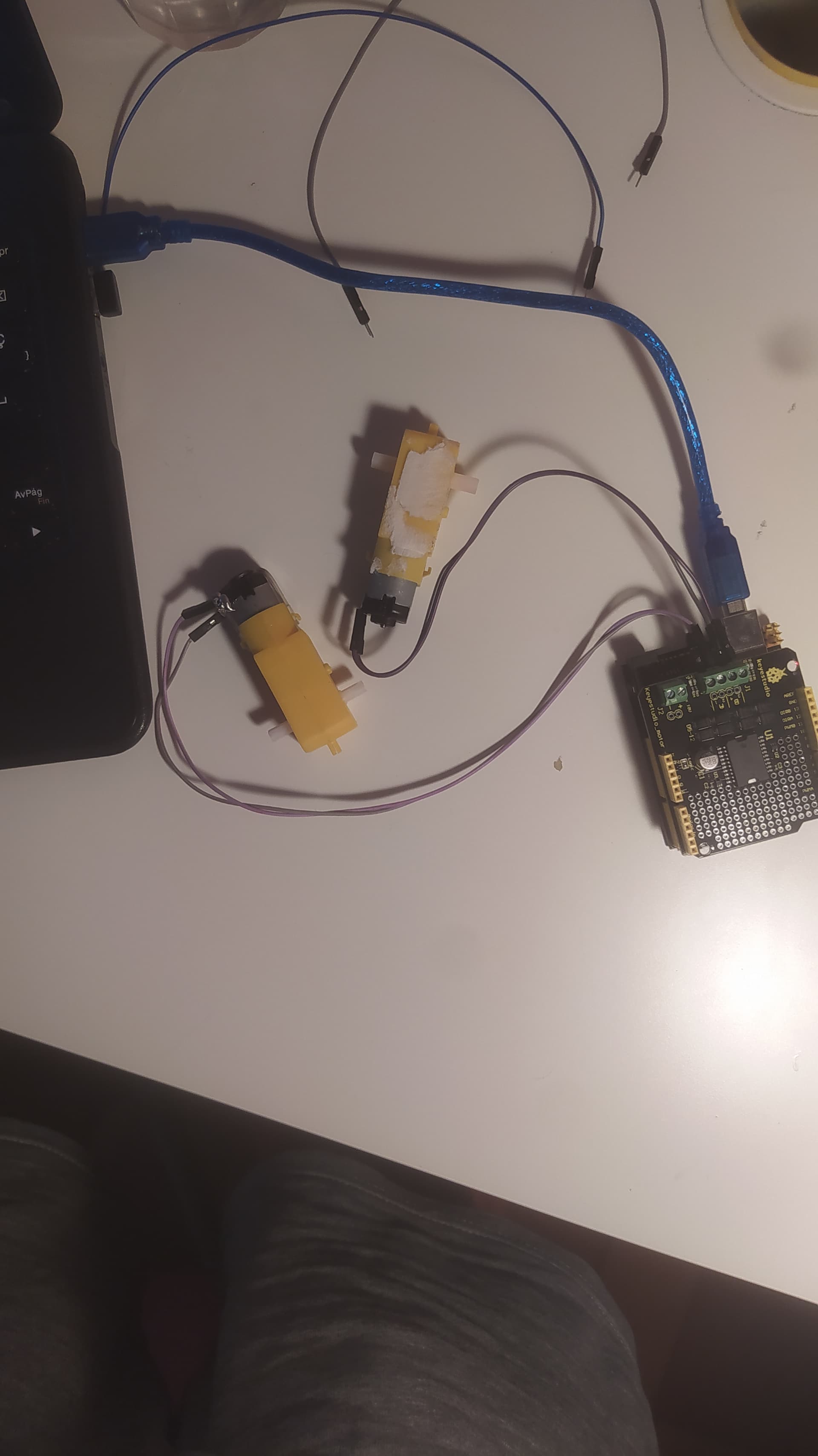
I send you also this picture if there is any problem with the motors connections, but I don't think so because it is an easy placement of the motors.
In the Arduino UNO this lights are turning on so I just wonder if here is the problem.
The lights are the D13 and the PWR.
I know that I am not the best student but I am trying hard with this. I am sorry if you feel that you are wasting your time with me. But I will try really hard because this goes well.
I really thank you,
-jj
if using the code from the manufacturer keystudio
https://wiki.keyestudio.com/Ks0007_keyestudio_L298P_Motor_Shield
does not work. It is very likely that something with the hardware is wrong
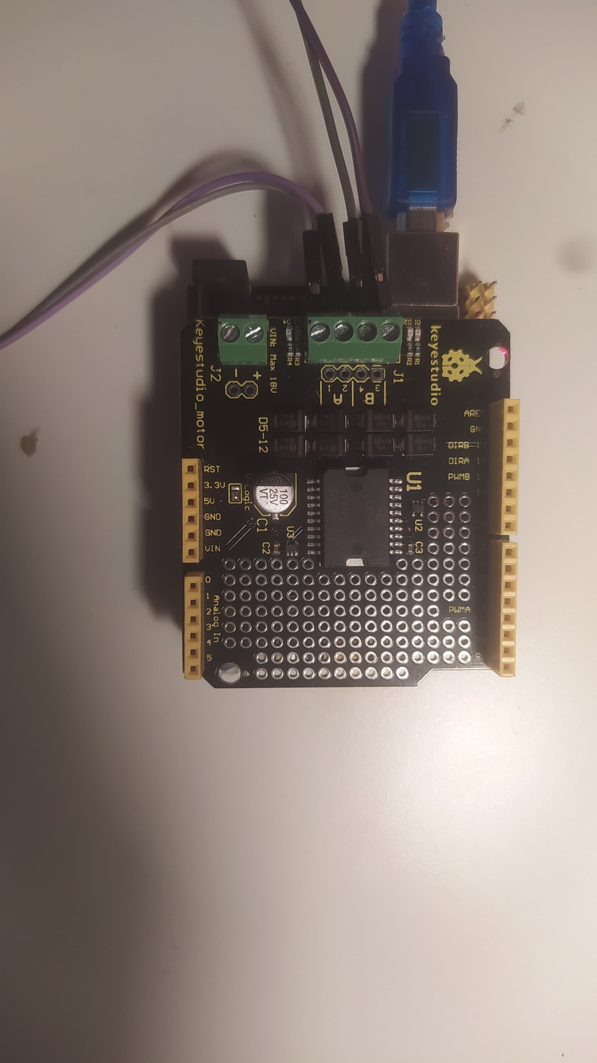
On this picture
the Arduino-Uno_Keystudio-clone and the Keystudio-Motorshield are only powereds by the USB-cable
It might be that the motors draw too much current for this situation.
use this code-version
int E1 = 3;
int M1 = 12;
int E2 = 11;
int M2 = 13;

void setup() {
  Serial.begin(115200);
  Serial.println("Setup-Start");
  pinMode(M1, OUTPUT);
  pinMode(M2, OUTPUT);
  Serial.println("IO-Pin cofig done exiting setup");

}

void loop() {
  Serial.println("Top of loop");

  digitalWrite(M1, HIGH);
  digitalWrite(M2, HIGH);
  analogWrite(E1, 200);   // PWM regulate speed
  analogWrite(E2, 200);   // PWM regulate speed
  Serial.println("M1,M2 HIGH E1,E2 200 done");
  Serial.println("now pausing for 8 seconds");
  delay(8000);
  digitalWrite(M1, LOW);
  digitalWrite(M2, LOW);
  analogWrite(E1, 200);   //PWM regulate speed
  analogWrite(E2, 200);   //PWM regulate speed
  Serial.println("M1,M2 LOW E1,E2 200 done");
  Serial.println("now pausing for 8 seconds");
  delay(8000);
  Serial.println("Botton of loop");
}
open the serial monitor to see if the code is executing as expected
best regards Stefan
Hi Stefan,
thanks for your fast reply.
I have just tried the code that you sent to me and the DC motors aren't working.
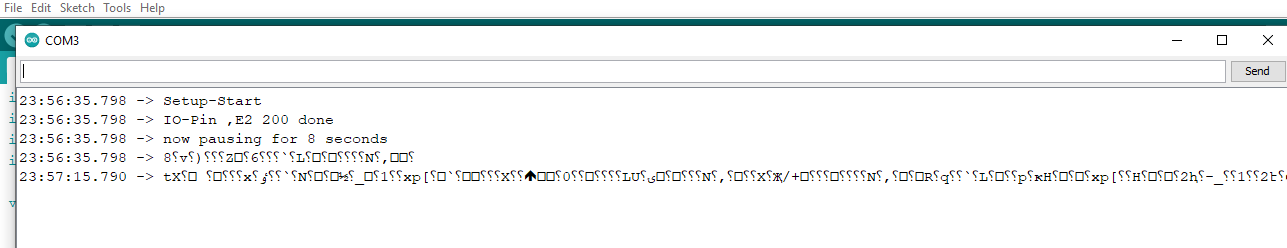
This is what the serial monitor is saying that the code is executing.
It doesn't look like a possible output for that very code on Post #36 by @StefanL38, there's no "IO-Pin ,E2 200 done" serial print! The "setup" function should print "IO-Pin cofig done exiting setup", then "IO-Pin cofig done exiting setup" after starting the loop, where it looks like misses "Top of loop" print, then "M1,M2 HIGH E1,E2 200 done" just before "now pausing for 8 seconds".
Please, if you make changes to a test code, just either avoid to do that or post the "real" code you actually used, together with your test results.
You're right, and (without knowing that shield) that was one of my concerns.
So, after a quick check, I have now seen THIS official Keyestudio video, where it is clearly powered via the two "external power" connectors:

This topic was automatically closed 180 days after the last reply. New replies are no longer allowed.