Arduino busted. Want to help a lost soul to understand what part of it broke?

Hello, first of all, you should know that I'm not what you could call a hardware "hacker", yet i understand as much as a physics graduate can understand about circuits and stuff. The kind of help i'm looking for is probably for those who can wear the name hardware hacker. Nevertheless, any kind of input would be appreciated.

I've been tinkering with a garduino project, i was trying to add a battery backup pack to it, i had a relay powered by the dc mains, which would switch to battery power when the mains were out. Since the time it took for the relay to switch off was too long and forced the arduino to reset, I had to add a Zener diode between the 9v rail coming from the transformer and the relay.

Well, in a nutshell, i should've studied better what are zener diodes. The guy in the store misunderstood me and suggested a 9v Zener, so when i conected the 9v transformer the zener made the relay flicker madly for one second approximately before i reacted and disconnected the system. Needless to say, it was a disaster. I spot solder on the board which must've blasted off the home-made shield connected to the board (the solder from the arduino seemed untouched though, it appears it all came out from the shield).
Since i'm a dumb monkey who holds hope as an emotion, i plugged the board alone to the computer. The "ON" led wouldn't even turn on..

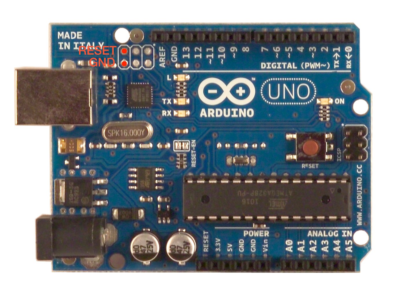
After a lot of scrutiny on the board, i realized there was a chip with a blob of solder on their terminals. I don't know what's the chip doing on the circuit, it's the tiniest one with six legs (three on each side) right in the middle of the big power regulator, the quartz crystal, the ATmega chip and the big capacitors besides the dc plug.

With a little bit of flux, i managed to clean the site from that nasty solder, so what does monkey do? Plug it again! hell yea! i can see the "ON" light turning on again, i can reset the arduino which causes the 13 pin led to flicker (that means the bootloader is there right?) and my linux system even recognizes the board when plugged in. It names it arduino and all..
Yet, i can't upload any code to the board. When i try to do it the tx/rx leds won't turn on (the arduino sits there silently) and the arduino program returns with the errors:

avrdude: stk500_getsync() : not in sync: resp=0x00
avrdude: stk500_disable(): protocol error, expect=0x14, resp=0x51

what could it be? It looks as if the board can't communicate with the pc properly. yet, the device is being recognized and everything..

I'm not getting my hopes up about repairing the board, but i'm willing to learn as much as i can from this.. so any help would be appreciated

I will post pictures of the board and a schematic of the shield when i have time to do it. Just ask for any extra information you need or pics youd like to see.

Did you unplug the shield and try just the Arduino. If so then the next thing to do is buy another atmega chip with boot loader and replace the one you probably fried.

First step is to run the loop back test, there is a sticky around here somewhere to show you how to use it. If it says communications is ok then just buy a replacement 328p chip with bootloader installed (around $6). If the test says that comm is not working, your probably better off just buying a new board.

Good luck;

Lefty

Yea, i did try the board by itself.
Before i cleaned up the solder on the tiny chip i mentioned (the one with six legs near the dc plug) the board wouldn't turn on, and now it does ((btw, what does that chip do?)).
I think that the chip (the main one) is working too, since i can press the reset button and led 13 blinks for a moment. I'm gonna try and check if my old code is still working when i get more time, but for now, I only have the led 13 blink as proof it might be still working.
The serial communication fails altogether, so no serial viewer to check the chip. But i could check it by connecting leds to where the pump control was before to see if they turn on when i raise the voltage on the proper analog pin.

P.S.: i know that i should just replace the board (and i will in the near future), but i'd like to try and repair this one (or at least learn what's broken) just for knowledge's sake.

That is weird, I do not see a 6 pin SMT device in the area you describe. There is a 5 pin 3v3 voltage regulator...

Anyhow, as retrolefty suggested, you might want to test the loopback that is described in Installation & Troubleshooting to see if your communications chip (Atmega8u2/16u2) is in working order. It is the chip that takes USB serial and converts it to TTL serial and sends it to the Atmega328.

Regardless if it passes or fails, I would recommend getting a second Arduino so that you could use it to troubleshoot the "busted" board at a later date. With the second board, you can program the bootloaders and read communications. Maybe a breadboard Arduino and FTDI communication?

here i took a picture of the arduino marking the little guy that couldn't run.
and as for the loopback, i it failed.
I'm not sure if led13 should blink at regular intervals or if it does this only once when i have my reset pin jumped to GND. Maybe i just have a broken jumper?

aaah, spcomputing, i can see now why you couldnt find the 6 legged smt.. it had 8 legs :blush: ... and thanks for the breadboard suggestion. I'm thinking it could be really instructive to reconstruct an arduino using this one for guidelines :slight_smile:

update: i tried the loopback test with another jumper and it failed again. I even tried holding the reset button over for a long time and nothing.

big update: I don't have a led around, so i'm trying the digital outputs that should be 'on' with a capacitor. HOHO! it appears that my old code is still running inside the 328p. The communication is the only thing off. Could it be because of a malfunctioning whatever-its-called chip?

Ahhh returned... that is the operational amplifier on the 3v3 circuit (LM358). I would be lying if I knew what that actually does.

Just my observations, with a over-voltage situation, there could be lots of unseen damage. But...

Based off of your observations, the Arduino R2 or R1 (It is using the Atmega8u2 for comms) is enumerating to the PC. There is future "hope" in reprogramming that chip. (It should only blink a few to 7 times on reset)

Since you are getting the "bootloader blink", there is "hope" for the Atmega328. But, to fix any of this, you do need some extra hardware like a programmer (another Arduino will do well enough).

I see. So the amplifier should be cheap and easy to find?
I'm gonna get some tools (could you believe my tester and solder broke just today?) and some leds to test properly the system.
IF this works, i'll take a dive and replace the amplifier, in the meantime i'll try to read about it to see if this could be the problem.
That's all i can do for now.
Thanks. i'll keep you updated :slight_smile:

Looking at the arduino schematics i've come to an hypothesis. Some of the pins of the amplifier were shorted, if the pins 2 and 3 were at short, the gnd wouldve raise the voltage to 3v, making the 380p unoperable. Fixing this let me turn on the device, so the damage is somewhere else.
I'll get another arduino and try reprogramming the atmega :slight_smile:

Just remember, bring up the 5v0 circuit first, then toy with the 3v3. You "should" be able to bring the 5v0 circuit up without the 3v3 causing you too much trouble. The 3v3 is just a convenience for shields that use low voltage. The Garduino system does not look like a 3v3 dependent system.

Ok, since i know now that i'll have to get another board, i was interested in building the pinguino from hackinglab. Do you know if the DFU mode i have to enter to load the atmel recovery software should be available on the PIC 18F2550 ?
one last thing, the link on that this site provides is redirecting me to atmel's homepage, http://www.atmel.com/dyn/products/tools_card.asp?tool_id=3886, and when i look for the ATmega8U2, it comes up with a bunch of results and they're all named the same.. D:

Ok, since i know now that i'll have to get another board, i was interested in building the pinguino from hackinglab. Do you know if the DFU mode i have to enter to load the atmel recovery software should be available on the PIC 18F2550 ?

Uh, no. We are going to try using AVRDUDE to get onto those 2x3 male headers. If you are going to go a different direction, I would recommend getting a USBTinyISP then. The Atmel FLIP could work since you are enumerating but it will not help the Atmega328:
http://arduino.cc/en/Hacking/DFUProgramming8U2

Lets just stick to the AVR type chips like the 328p for the troubleshooting process. We can play with the PICs later (I actually have a 18F2550 earmarked for the project).

Here is the 8u2 overview:

Ok then. I'll order a new arduino soon enough. It may take a while though until the board arrives.
In the meantime, i could try to get a boarduino up and running using my now war veteran 382p chip.
I'd rather not reflashing the arduino bootloader if it's not necessary.. should i still follow the Ducimilanove boarduino instructions or are there some uno board instructions around? does it make a difference for the bootloader?

rangua:
Ok then. I'll order a new arduino soon enough. It may take a while though until the board arrives.
In the meantime, i could try to get a boarduino up and running using my now war veteran 382p chip.
I'd rather not reflashing the arduino bootloader if it's not necessary.. should i still follow the Ducimilanove boarduino instructions or are there some uno board instructions around? does it make a difference for the bootloader?

You will not be able to complete and breadboard Arduino without a USB2UART like FTDI or Silicon Labs converter. While you are waiting you could try to reload the Atmega8u2 with FLIP. All you need is a 10k resistor and follow the DFU firmware update instructions.

http://arduino.cc/en/Hacking/DFUProgramming8U2

I do not believe we are going to get away from re-flashing. There is no easy way to repair a bootloader other than a reflash. Don't worry, its simples. Nick Gammon has a fantastic programming sketch:

Here is a good tutorial on setting up an Arduino on a breadboard. We will use the Uno bootloader (just means it is small and fast compared to the Duemilanove bootloader).
http://itp.nyu.edu/physcomp/Tutorials/ArduinoBreadboard

Ok, the thing is i don't have a credit card which i can use freely, which really hampers my ability to buy from the internet. Also, i live in southamerica, which makes makes it even harder to get some components.. Can't i get away without the usb connection? i have a serial port on my pc..
edit: i don't see any terminals on the back on the board, could it be that on the R3 UNO they moved them at the front of the board?
edit2: comparing my board with the one in http://arduino.cc/en/uploads/Hacking/Uno-front-DFU-reset.png (where the 10k resistor should be soldered on the back) i can check that the terminals i thought where the ones are also on this one. but i can see also that i have an extra resistor in that area. Could it be that the UNO R3 already has the resistor soldered in position?

It's only a small point, but if you updated your location it may help. There are some very knowledgeabe people in your part of the world (continent!) and they may be able to offer advice on obtaining parts.

dannable: thanks for the tip. doing it now

That is fascinating, I have an R3 and there is nothing back there. Lets skip that as I carefully went through the instructions and they stink.

Ok, first thing to do is download and install FLIP (I am assuming you are running Windows or Linux).
After FLIP is installed, plug in your Uno to the USB.
Short the pins 5 & 6 on the Atmega8u2:

This should initiate a "New Device Detected" event, manually select the driver folder from the Programs Files\ATMEL\FLIP 3.4.7\USB
(Should install the Atmega8u2 driver and it will require a reboot)
After rebooting, open the FLIP 3.4.7 program and click the Chip Icon and select the Atmega8u2 and click OK.
Now, click the USB Cable and click "Open".

If you get this far, get a screenshot and post it here.

It is showing signs of beign ALIVEEEE bahahaha
i've come as far as you said, installed the driver and i think im ready to run the flip software.
heres a screenshot of the device manager

by the way: the 4 and 5 pins correspond to the two pins on the icsp header closest to the usb on my board. check the picture for reference

devicemanager.png

Ok, im trying to run the flip software to upload the firmware and i can't get it to work.
I'm using windows now, rebooted, and replugged the arduino uno shorting the 4-5 pins on the 8u2. The device once again shows up as a usb device.

When i open the flip software, it asks me to pick the model of the chip, which i do, and then asks for the communication. At this point i pick usb (the only non-grayed option) and it prompts me with the window on the first pic. When i click Open, it tells me "Could not open USB device".
I tried loading the hex file, and here too i ran into a problem. i copy/pasted it on Notepad++ and saved it as UNO-dfu-8u2.hex, but when i try to load it on the flip it tells me the address is out of range :S
how does this work? :~
i had the wrong hex file. Hex file loads up correctly, still no communication :frowning: