Arduino custom board ATMEGA328 keeps changing signature [solved]

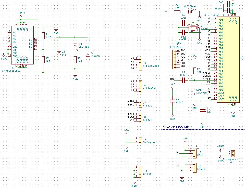
We have made a custom PCB based on Arduino Pro Mini schematic for our project. We are trying to use Arduino as ISP to upload the bootloader to the chip, but when we do so, the signature reported by avrdude changes every time we run the program. It also does not match the actual signature (it's usually a combination of F's and 0's, e.g: 0x00FF00). Is this due to faulty hardware or something else? Should we try to replace the chip with another one?

avrdude: Version 6.3, compiled on Jan 17 2017 at 11:00:16
         Copyright (c) 2000-2005 Brian Dean, http://www.bdmicro.com/
         Copyright (c) 2007-2014 Joerg Wunsch

         System wide configuration file is "/home/athul/opt/arduino-1.8.5/hardware/tools/avr/etc/avrdude.conf"
         User configuration file is "/home/athul/.avrduderc"
         User configuration file does not exist or is not a regular file, skipping

         Using Port                    : /dev/ttyACM0
         Using Programmer              : stk500v1
         Overriding Baud Rate          : 19200
         AVR Part                      : ATmega328P
         Chip Erase delay              : 9000 us
         PAGEL                         : PD7
         BS2                           : PC2
         RESET disposition             : dedicated
         RETRY pulse                   : SCK
         serial program mode           : yes
         parallel program mode         : yes
         Timeout                       : 200
         StabDelay                     : 100
         CmdexeDelay                   : 25
         SyncLoops                     : 32
         ByteDelay                     : 0
         PollIndex                     : 3
         PollValue                     : 0x53
         Memory Detail                 :

                                  Block Poll               Page                       Polled
           Memory Type Mode Delay Size  Indx Paged  Size   Size #Pages MinW  MaxW   ReadBack
           ----------- ---- ----- ----- ---- ------ ------ ---- ------ ----- ----- ---------
           eeprom        65    20     4    0 no       1024    4      0  3600  3600 0xff 0xff
           flash         65     6   128    0 yes     32768  128    256  4500  4500 0xff 0xff
           lfuse          0     0     0    0 no          1    0      0  4500  4500 0x00 0x00
           hfuse          0     0     0    0 no          1    0      0  4500  4500 0x00 0x00
           efuse          0     0     0    0 no          1    0      0  4500  4500 0x00 0x00
           lock           0     0     0    0 no          1    0      0  4500  4500 0x00 0x00
           calibration    0     0     0    0 no          1    0      0     0     0 0x00 0x00
           signature      0     0     0    0 no          3    0      0     0     0 0x00 0x00

         Programmer Type : STK500
         Description     : Atmel STK500 Version 1.x firmware
         Hardware Version: 2
         Firmware Version: 1.18
         Topcard         : Unknown
         Vtarget         : 0.0 V
         Varef           : 0.0 V
         Oscillator      : Off
         SCK period      : 0.1 us

avrdude: AVR device initialized and ready to accept instructions

Error while burning bootloader.
Reading | ################################################## | 100% 0.02s

avrdude: Device signature = 0x00ff00
avrdude: Expected signature for ATmega328P is 1E 95 14
         Double check chip, or use -F to override this check.

avrdude done.  Thank you.

atmega arduino power supply.JPG

Almost certainly an issue with your wiring.

or a floating input.

25thHickman:
We have made a custom PCB based on Arduino Pro Mini schematic for our project.

Rather odd thing to do to start with.

Making a custom PCB, the most sensible thing to do is to simply mount a Pro Mini to it as a daughterboard. Makes it all much simpler, cheaper and you use a "standard" programming adapter to operate it via the bootloader. Yes, I know the regulator on the Pro Mini (as well as the "pilot" LED) is superfluous, but it simply doesn't count. :grinning:

Oh well ... :roll_eyes:

wvmarle:
Almost certainly an issue with your wiring.

Thank you for reply. I assume you mean the an issue with the schematic of the PCB. I went through the schematic again but I could find no fault in it, if you could offer some insight on how to diagnose the problem it would be much appreciated.

Based on all the replies above - it may be time to post your schematic that was used to generate the PCB.

Wiring - as in the circuit, the PCB design, other things that are connected, connection to your programmer... But what would I know. You're not offering any details.

wvmarle:
Wiring - as in the circuit, the PCB design, other things that are connected, connection to your programmer... But what would I know. You're not offering any details.

lastchancename:
Based on all the replies above - it may be time to post your schematic that was used to generate the PCB.

Sorry about that. I've updated the question with an image of the schematic.

25thHickman:
Sorry about that. I've updated the question with an image of the schematic.

Is that the real schamatic ?

Its labelled Pro Mini and shows no other components, not even the ISP connector one would presume you are using ?

Unfortunately, the pieces of the (decent) schematic you’ve posted - don’t show your ISP programming interface... which seems to be the problem you’ve identified. Along with anything else that touches the SPI/ISP pins.

Also to help others help you, it’s kinder to put the images as attachments (like you have), then edit the post - and link the images inline with the post.
There’s a guide in the how-to section of the forum stickies.
We’re getting there.

Here's the full schematic (I've also updated it in the question).We haven't used any of the other pins besides D6 and D7 (connected to ultra-sonic sensors) . We are not using a dedicated ICSP connector, but instead we are connecting the pins used by the ICSP directly to the UNO which we are using as the ISP (arduino as ISP sketch). The connections to the UNO have been detailed below.

UnoPro Mini
Programmer -------------- Target
5V (vcc) ------------------- VCC
GND ------------------------GND
Pin 10 ---------------------- DTR
Pin 11 ---------------------- MOSI
Pin12 ---------------------- MISO
Pin 13 ------------------- -- SCK

Sorry for all the back and forth. I'm new to this :frowning:

25thHickman:
Pin 10 ---------------------- DTR

That will not work.

Pin 10 needs to be connected to RESET on the target.

Thank you very much that made it work. Connecting to the RESET pin directly fixed it. If you could explain why the DTR and RESET signals are so different? Even though the difference I could spot was a capacitor (C2) connected in series to it?

25thHickman:
Thank you very much that made it work. Connecting to the RESET pin directly fixed it. If you could explain why the DTR and RESET signals are so different? Even though the difference I could spot was a capacitor (C2) connected in series to it?

RESET need to be held low continuously during ISP programing.

For using the serial bootloader only a pulse is required, so when the serial adapter pulls DTR low a short rest pulse only goes onto RESET.

Now reflect on how much time would have been saved by the volunteers on this forum if you had been prepared to reveal at the outset what your schematic and connections actually were. Even when you eventually posted a schematic it was a redacted version, which did not show the connctions you were using.