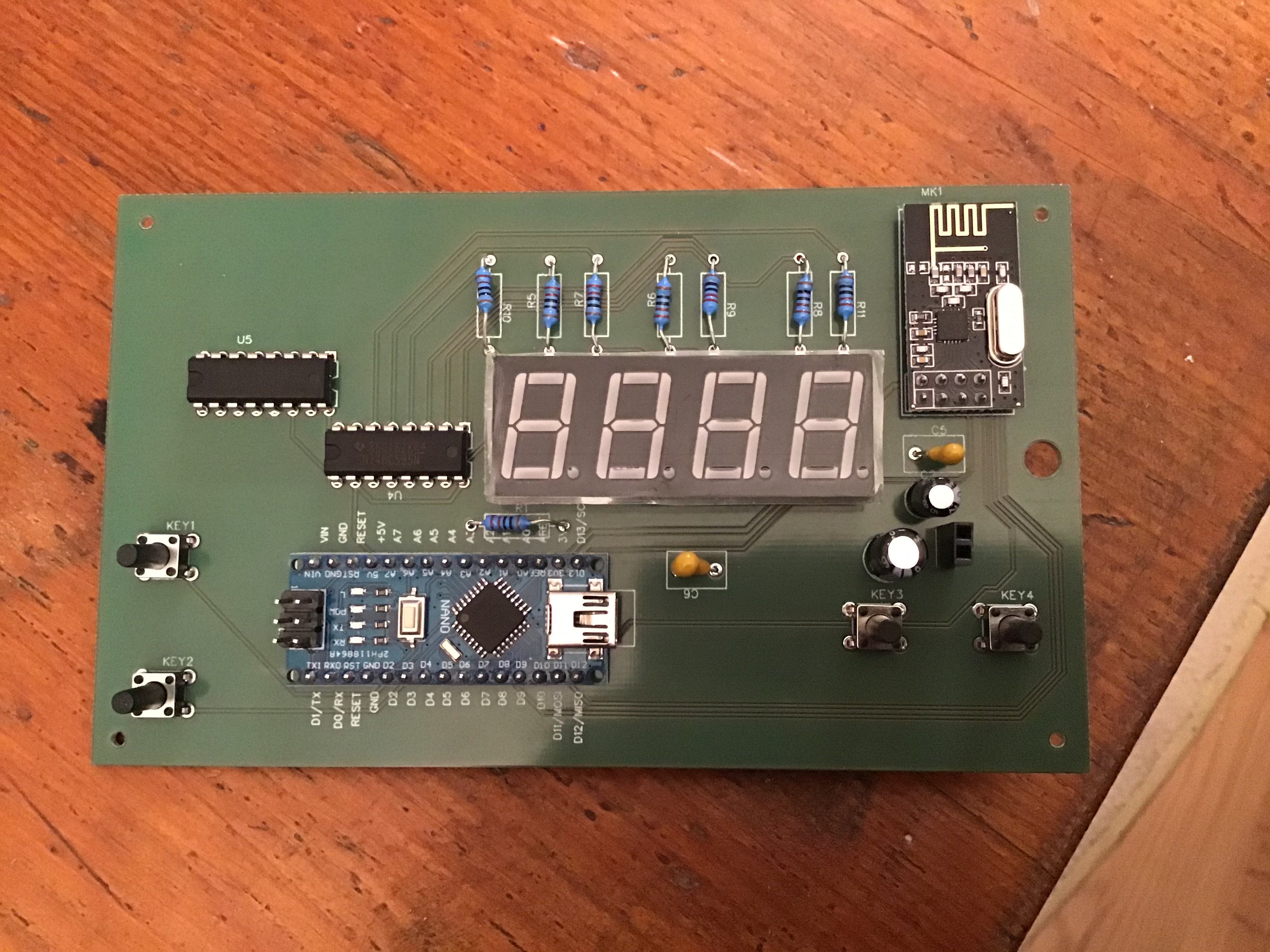
Hi, I'm building an RC car transmitter. I soldered components onto the PCB, which I designed, link is here (EasyEDA(Standard) - A Simple and Powerful Electronic Circuit Design Tool), GND is connected by copper pour on the top and VCC is connected on the bottom by copper pour.
When I connected Arduino NANO to battery it did't function, so then I tried to connect it do computer, but any diode did light up on the Arduino. What could be the problem? In my opinion, the problem could be that I connected GND and VCC of the battery reversely, but I'm not sure, whether I did it that way.

If you connected the power the wrong way you might have damaged the Nano. Is it soldered to the board or is it plugged into headers? If you remove it and power through the USB connector and it doesn't work then I think you have your answer.
Is the device in the top right WiFi? You will possibly have problems with the signal because there is copper directly below the aerial. If you have a problem use headers to lift it up from the board. Ideally there should not be copper underneath.
I would make the board with no pour in the top right corner or hang the aerial over the edge. Or both.
Thank you and yes it is Wifi. So should I remove the NANO and replace it with another one? Is the PCB layout ok?
Is the PCB layout ok?
I'm no expert but in general terms it looks ok. However, I have no way to know if it matches your circuit.
You should carefully check that all the connections are as you expect them to be.
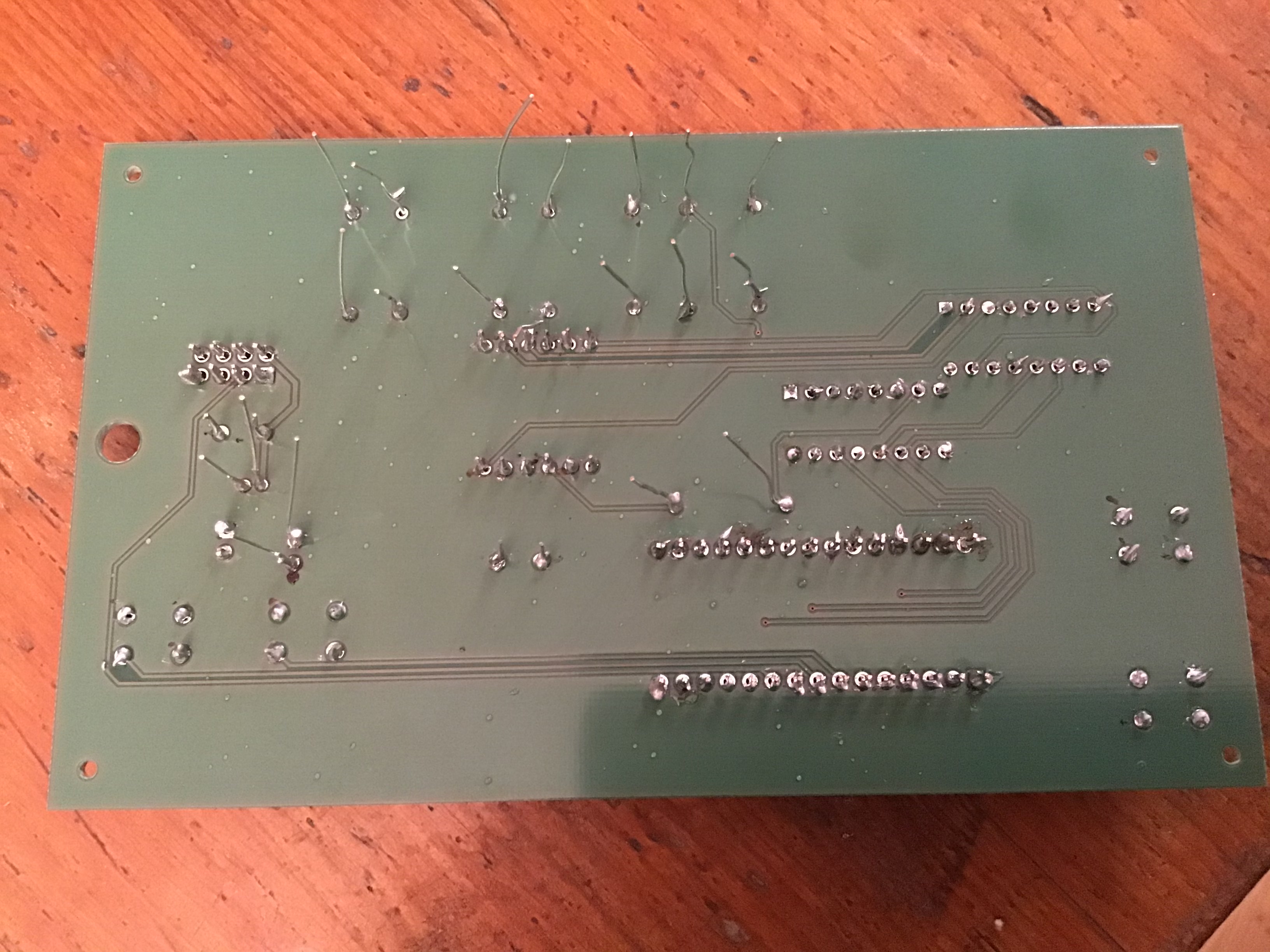
Larry is right about your soldering, I can see a lot of very suspect joints.
The radio won't work, or will have only very short range, if there is any copper on the PCB underneath the "F" antenna trace. It looks like you have two solid layers, so you'll probably need to design and order another board. Or cut away a chunk of it, under the radio.
Obviously, you should check all the other functionality first, and find the other mistakes.
If I understood your initial post is seemed to say:
Your first test was with a battery and nothing worked (even the LED?)
Your 2nd test was via the USB connection and the LED light.
This would suggest the board is not providing power to the Nano
To test the Nano, from the USB connector download the blink example and see if that works.
As suggested above, no offence but you soldering is horrible. On the bottom the 2nd in on the top left looks like it is not even soldered.
I don't know if your iron is too big, or too cold or you technique needs developing. As larryd showed the solder process is rather quick if the iron is the right temp. I can usually heat and solder in ~ 2 seconds.
Regarding you PCB. It looks OK but I would:
- increase the width of the traces. No need to use the minimum if you have plenty of room
- increase the via diameter (drill and annular ring) for the same reason as #1.
- I would add some pads for ground and Vcc to make it easy to measure them.
If you have a multimeter it should be easy to check if the board is getting power. If not I recommend you get one. For this type of troubleshooting you can get by with a real cheap one. It really only needs to read 5V, 12V and ohms. Accuracy is not an issue as the measurement don't have to be precise.
Or lack of it.
Three words.
FLUX FLUX FLUX
Technicians best friend.
@JohnRob
When I connected the battery nothing happend and none of the diodes did light up. When I connected the USB, none of the diodes on Arduino did light up and computer couldn't find a port.
windoze_killa:
FLUX FLUX FLUXTechnicians best friend.
Yeah, nah.
I have soldered 50+ years WITHOUT FLUX (consumer electronics technician).
Soldering vias/pins with good resin-core electronics solder and does not need flux.
It could even make a bigger mess.
It's all about technique.
- don't put solder on the tip. It just burns off the flux inside the solder, making it useless.
- heat both via and pin with a clean/dry tip for 1-2 seconds, and apply solder to the pin/via, NOT to the tip of the soldering iron.
- hold for 1-2 seconds, so it flows inside the via.
- quickly remove the soldering iron.
I do have flux, and sometimes use it when replacing smd parts.
Leo..
Wawa:
Yeah, nah.
I have soldered 50+ years WITHOUT FLUX (consumer electronics technician).Soldering vias/pins with good resin-core electronics solder and does not need flux.
It could even make a bigger mess.
It's all about technique.
- don't put solder on the tip. It just burns off the flux inside the solder, making it useless.
- heat both via and pin with a clean/dry tip for 1-2 seconds, and apply solder to the pin/via, NOT to the tip of the soldering iron.
- hold for 1-2 seconds, so it flows inside the via.
- quickly remove the soldering iron.
I do have flux, and sometimes use it when replacing smd parts.
Leo..
I have been a technician for over 40 years, 8 of those were teaching soldering and mechanical connections to DOD2000 standards (NASA standards). I also taught multilayer PCB repair.
Flux in solder is not sufficient for an acceptable joint to those standards, might meet consumer electronics standards.
PS. If you can solder it it is not a via, it is a plated through hole. Vias normally are covered with solder resist.
@JohnRob
When I connected the battery nothing happened and none of the diodes did light up. When I connected the USB, none of the diodes on Arduino did light up and computer couldn't find a port.
Unfortunately is doesn't good. Like you suspected you likely toasted the nano.
I Can't tell if the Nano is soldered in or not. I suspect it is. When replacing I would put female strip headers on the board so you can plug and unplug the Nano
Just an aside since there is a lot of talk about extra flux.
IMHO one seldom needs added flux. The flux in the solder is nearly always adequate. The only situation where you might need added flux is if repairing something really old and oxidized. Usually this is something like old non plated copper wire.
While soldering training at Redstone is cool, I don't recall they included soldering OLD parts and wires.
Hi,
Do you have a DMM?
Can you please post your schematic and PCB pattern in the post please?
The EDA link does not work, and it is easier for the information to be presented here.
Tom.... ![]()
Are people looking at the soldering ? !
Let's hope not, for their sake...

I couldn't look. It was too painful.