I am trying to make my first custom PCB but apparently, there's something wrong w/my schematic because I keep frying Arduino Nanos when I plug in both 12v external power to VIN and also plug in the USB to my PC. I have attached my schematic below, which I made via EasyEDA. I ordered the board from JLCPCB and it works great as long as I only plug in the 12v external power. However, if I also plug in the USB connector to update the code, I let a bunch of smoke out and that's that. If I ONLY plug in the USB, it's fine, but the A4988 doesn't have any power to actually drive the motor. Can anyone point me in the right direction? Thanks!

Show us the PCB images exposing all traces.
Did you set the the current limit of the driver ?

If you mean the pot on the A4988, yes it's set to max: 2A (12v supply is 3A). I'll recheck it and reset it after I unsolder this smoked nano and replace it with a new one. Hopefully, get to it tonight.
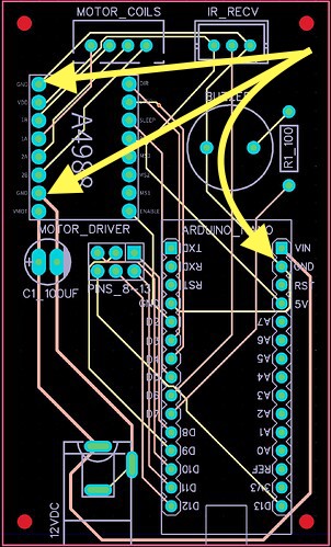
Don’t rely on the internal GND connection in the driver chip.
Did you set the current limit ?
don't think it's a good idea to run 2 power supplies..
get a usb power block..
sorry for the loss.. ~q
are the grounds connected together? s there a voltage difference between the USB ground and the 12 VDC ground?
if you use the V IN pin you bypass the voltage regulator. you should use 5V at the V IN pin
Pointless. Feed the input of the regulator with 5V? Let's see where Arduino recommends that!
The accepted practice is to feed the 5V pin with external 5V, if you're powering anything. The Vin pin should be used only to power the Nano with voltages between 7V (minimum) and 15V(Regulator maximum). Look up the datasheet for the regulator, don't believe the marketing BS on the Arduino website about "6 - 20V".
If you must use Vin, you want to provide a low voltage, say 8V, because that reduces the power dissipation on the regulator, allowing you to draw more current.
1 Like
Use smd diode. This happened to me, this is how I solved it. Schottky smd diode and filter capacitor reduce voltage drops and solve the problem. You can supply voltage from both the PC and the outside at the same time. Give 5 volts, the diode passes the voltage in one direction, don't you need to supply voltage in the 12v direction?
do not use a module 12v RAW (vin) dir input like promini
Design it completely as vcc 5v, be sure to check, you will burn the chickens.
1 Like
The tracks are way too thin, especially those carrying power. PCB makers don't charge more for wider tracks. All the ground connections should be joined, preferably by using a ground plane, which means filling on one side of the PCB all the empty space with copper connected to 0V.
While I don't see anything specifically wrong with your schematic it would be easier to read if the connections were made with lines rather than the 'join the dots' way you have done.
1 Like
Thanks for all the replies!
Yes, I set the current limit to max (it says 1A per coil x 2 coils = 2A). FWIW, the motor is not running at all when it fries. When I plug the USB in while the 12v is already connected, smoke immediately emerges from the Arduino before I have time to connect to the Serial monitor.
I'm unsure what you mean by "do not rely on GND connection in the driver chip." I see your arrows, but I don't understand what they are implying/suggesting. I purposely connected all of the GND pins to each other as I thought that was the correct thing to do. I could redesign to use a dedicated GND PCB layer if that would help.
Initially, I was concerned about separating the GND of the 12v from the GND of the 5v. However, I read many threads now and understand that they can (and should) share the same GND, as they are connected to each other internally on both the A4988 and Arduino anyway.
This is for an art piece that will go on the wall. I want to be able to plug it into a nearby wall socket to avoid batteries. I was hoping to use a single DC power supply to power everything.
I thought if I supplied 12v to VIN, then I could use the 5V pin on the Arduino to power the A4988 logic, buzzer, and IR sensor. Should I instead be using a separate 5v step-down/buck converter to power said components? Or just go with a lower voltage (i.e. 9V) DC adapter?
Again, it works perfectly as-is as long as I don't plug the USB in simultaneously, so feel like I'm missing some key understanding of how the USB power and external power sources interact.
Re: The Schottky diode, where in the circuit would I add this, exactly? Does this imply that the current is flowing in the reverse direction somewhere when I have both plugged in? As you can prob tell, I am very new to all this and am doing my best to wrap my brain around it all.
I included a screenshot of all the lines above. Unless you meant something else.
So, you've really thrashed this by replying to various commenters all in one comment, then directing it to me. I'll try to clarify my content, and comment on the others where I know something about the topic. Ya get what ya pay for around here!
- if it's smoking, it's dead. Don't repeat that experiment, no new data will ensue. But don't jump to replace it and try again quite yet...
- The PCB traces are woefully inadequate. There's lots of guidelines on the web, but I'll give you a thumbnail to work from. Using 1 oz copper, I would plan on 100 thou per ampere of current; if your driver is sinking 2 amperes, that's a 0.2" wide trace, except where you have to narrow it around other devices(minimize that). Now, others will quibble about widths, but like I said, find some pro advice on the web. The point is, a ten thou trace is not a power trace. Period.
- High current runs and low current(signal and control) should be separate until they return to the power supply(s).
- for the Arduino, either 12V, no peripherals, or 8-9V with what you've listed and no more.
- I see no connection between your 12V common and the 5V common (unless the 4988 has two ground pins, and you're taking advantage of that, but that's then what Larry is telling you not to do). Provide a solid ground connection between GND of your 5V supply/Arduino and the 12V supply.
- make darn sure all your power supplies are DC, not AC or unregulated DC. That's a common, often fatal-to-device mistake. IF you have a DMM/DVM/ voltmeter of some form, measure the outputs with no load attached. If they're regulated DC, you'll get the rated voltage. If they're unregulated, they'll be much higher, and if AC then you'll see precious little on the DC measurement, but be able to see a healthy voltage on AC.
Still don't see a smoking gun, though - but one of these items could be it.
1 Like
Yeah, my bad. Not sure how I replied to just you, I was trying to reply to the whole thread. Still learning this forum's UI. Thank you for tolerating my noobness ![]()
-
Yes, I wasn't going to try and repeat the same experiment, per se. I have a couple more boards, so I just made another to test out all of the other functions and work on the code some more. I will avoid plugging both in at the same time for now.
-
EasyEDA indicates that the regular traces are 0.254mm wide (10 thou) and the 12v traces are .400mm (15.75 thou). I was unaware of that width per amp guideline, so thanks for pointing that out! I'll adjust them accordingly.
-
I think I understand and did make an effort to dedicate thicker traces for the A4988 driver. I'll make a better effort in my updated design to beef them up more and keep them separate.
-
I'm using a random 12v DC adapter I had lying around. It says Output: 12Vdc, 3.0A.
-
Ok. Yes after I read that the GND pins are all connected internally, I thought that would be adequate to just link them all, but I'll do a better job of dedicating GND and supply traces instead of stringing them all together.
-
Using a multimeter I tested the 12Vdc power supply I mentioned above. I get a steady 12.33v at the barrel/connector w/no load. Maybe I'll order a 9Vdc regulated adapter just to be sure.
Thank you so much for taking the time to respond to all these points. I'm not an electrical engineer at all (obviously); just trying to make a fun (and I thought simple) project to learn more about electronics. It was fairly easy to get a prototype working with the breadboard and jumpers. I now realize translating that to a custom PCB design is a bit more nuanced than I anticipated.
2 Likes
UPDATE: so I made another board but was unable to connect to program it. I realized the USB dongle I was using was getting extremely hot, so I ordered a new one which worked fine (and didn't get hot) and I was able to connect/program the new board. Just to test, I connected the old "fried" board (USB only), and it also worked with the new dongle.
So it seems like maybe the issue was with the USB dongle. However, I'm afraid to try connecting both power supplies again in case that is what actually fried the dongle in the first place.
Anyhow, I redesigned the board to widen all of the traces and will order a new batch soon.
Did you understand what @LarryD was explaining in post 4?
1 Like

You have a 5v line running next to a ground common. What is your resistance reading between 5v and ground?

Do you have a board with 5v disabled?
@jim-p Maybe? I interpreted his comment to mean to make sure I connect the two GND pins on the driver together on the PCB outside of the driver's internal circuitry.
@apf1979 No, 5V is enabled. I'm feeding the Nano 12Vdc to VIN and then using the 5V pin to power the other 5V components (IR sensor, buzzer, and driver logic). The resistance between the Arduino 5V and GND pins on the newly made board is 2.78 ohms, and on the "fried" board it reads 21.6 ohms. ![]() Also, yes I finally found the right Reply button, thanks!
Also, yes I finally found the right Reply button, thanks! ![]()
In the updated design, I have increased the width of all traces (using an online calculator), simplified the trace routing, and made sure all GND pins are connected together on the PCB.

1 Like
I think that everyone will agree that your new layout is MUCH improved.
2 Likes
At 12 volts that's over 4 amps. Yikes.
21.6 is still over 500 mA.