Hello everyone,
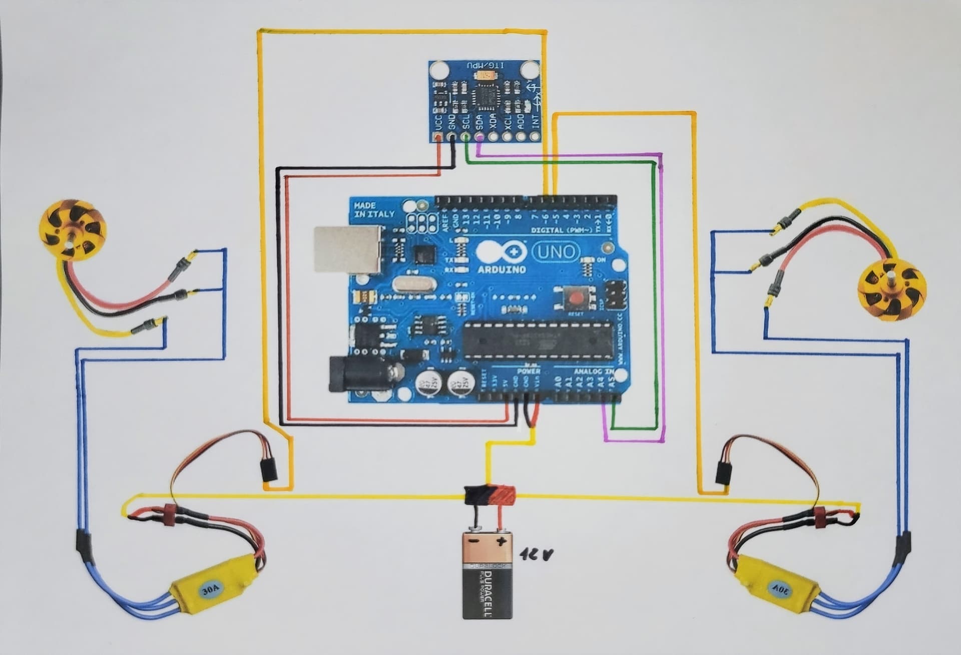
I have to make a drone with an Arduino Uno but I am completely new to this and I struggle to connect the different elements between them. I've found a video that shows the connections between the Arduino Uno, the 2 ESC and the MPU6050 but I don't really understand so I made up a blueprint that I show you below and I was wondering if anyone could tell me if this is gonna work or not and why pleaseee
Thank you for your help
1 Like
Hi @aquarius66
You'll most likely require a require LiPo (Lithium Polymer) battery plus charger, to power your drone. The voltage output from a LiPo depends on the number of cells 2S, 3S, etc... For example a fully charged cell outputs around 4.2V, therefore a fully charged 3S will output 12.6V.
I'd suggest powering your Arduino via a voltage regulator (linear or switching). On my prototypes set the regulator output voltage to around 8 to 9V. If your drone is quite small and you're using a 2S battery (at 8.4V), it's possible to power the Arduino directly from the LiPo through Vin.
The wiring harness configuration is also important. Power and ground wires from the ESC should go straight back to the battery. There should also be a common ground star point for the Arduino and ESC signal ground lines back to the battery as well.
Regarding the ESC signal lines, if your drone happens to be a quadcopter or other (non-servo) multi-rotor configuration, drive the ESCs with 490Hz PWM signals using the Arduino analogWrite() function. On the Arduino Uno these can be found on pins 3, 9, 10 and 11.
To control the aircraft you'll also require some form of receiver.
A good introduction to building a drone is Simplecopter's Tricopter build tutorial. It uses a KK2 flight controller rather than an Arduino, but the principle is the same:

1 Like
Okay thank you so much for your answer because I wasn't sure about the powering so I will follow your advice. However, I did not exactly understand what you mean here : "Power and ground wires from the ESC should go straight back to the battery. There should also be a common ground star point for the Arduino and ESC signal ground lines back to the battery as well."
Should I connect the other grounds (I mean the ones that are not connected in my blueprint) of both ESC to the ground of the Arduino ?
Hi @aquarius66
My apologies, what I was trying to say is that you'll require some sort of power distribution hub that connects the battery out to all the ESCs. The ground return paths from the ESCs should go directly back to this hub and not through the flight controller, or in your case Arduino.
In early multi-rotors builds this was achieved using a wiring harness with a spliced power cable from the battery to the ESCs, or alternatively using a rudimentary Power Distribution Board (PDB). The power (and ground) to the flight controller was usually provided by one of the ESC's 5V BEC (Battery Elimination Circuit); in electronics world the BEC is simply a voltage regulator (linear or switching).
The Simplecopter tutorial video I showed above describes the cable splicing method.
Nowadays, more modern builds use a PDB with battery and ESC solder pads, built-in switching power supplies at various voltage levels that can power the flight controller plus any FPV Camera/Video Transmitter (VTX), as well as including battery current sensing capability, for example:
There's quite a lot of information including wiring diagrams online. The Oscarling website is a very good source of (the latest) information:
Here my five cents:
-
Power supply: as mentioned by other you have to wire in a way, that all components gets a power (e.g. from the LiPo battery)
-
the GND wire is always a common signal on all units, all components. It is the reference for all voltages supplied. You cannot have any component without connecting it to GND.
The GND connection should look like "a star" all combined together at the same point. And the thickest wire you can use: the thicker the GND wires - the better.
But when it comes to control servos, the ESC (for motor speed) - try to understand what "PWM" is: a pulse width modulation where the ratio of lows and highs determine how much a servo should move. The "duty cycle" of PWM sets the position of the servos, even on the ESC for the motor speed. Get familiar with PWM and duty cycles.
1 Like
Okay thank you for your answers, so if I understood, I should use something like that which is connected to the battery in order to power the ESCs (with the ground returning directly to the battery) and to power the Arduino.


Hi @aquarius66
You're image is spot on (I guess a picture speaks a thousand words). The wiring harness can be constructed using either a PDB as shown or alternatively by splicing the battery cable out to the ESCs and with thiner wires to the flight controller itself. The advantage of using a PDB is that they can contain a voltage regulator (like the Pololu one shown in your image) that can supply the flight control board.
Personally, I'd put the Arduino's PWM motor outputs on pins 3, 9, 10 and 11. That way you'll more easily be able to drive them at 490Hz with the Arduino analogWrite() function.
Traditionally, multi-rotors used a 490Hz PWM rather than 50Hz, the faster update rate saturated the ESC input filters (which at the time were designed for fixed wing and helis) and thereby made them more responsive. The filter would converge on the desired output more quickly. Obviously nowadays there are quad specific ESCs that support any number of protocols (Oneshot, Multishot, DShot, etc...), but the 490Hz standard still remains.
What Arduino pins you use for the receiver will depend on what type you're using.
@aquarius66 By the way, you'll also require a 5V to 3.3V I2C level shifter, to convert the 5V SCL and SDA signals from you Arduino to 3.3V used by the MPU6050.
This topic was automatically closed 180 days after the last reply. New replies are no longer allowed.