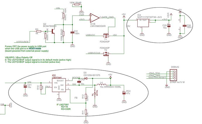
It is well known that the Due does not give good ADC readings. My experience is that deviation on 12 bit conversion can be +/- 50 ADC point, which is very unaccurate and sometime unusable for most measuring application.
I have tried a lot of methods found on different forum discussion (filtering with capacitor on both signal and on the power supplies 3.3V and 5V, I have also tryied the software averaging methods.. !) None of these method did work.
I also had doubts about the quality of the SAM3X processor convertor, but found good feedback from multiple sources.
I have also recalled that I had good results on Arduino Mega (10 bit ADC). and I have also noticed that when powered with USB via my PC the ADC results was much better....
So, I decided to donwload and have a look to the board schematic, and the problem appears very clearly...
On the Due board,they have decided to use a switching converter to down the Vin to 5 Volts, and then a normal voltage regulator to down the voltage to 3.3V.
The problem is coming from this design as the step-down DC/DC regulator, a LM2734Y (switching frequency of 550Khz) is sending noise all over the power lines of the Due board causing this innacurate ADC readings. (See the attached drawing). Very bad design from the Arduino engineers giving nightmares to users !!
To overcome this, I have then decided to not power the board via the Vin (the round board connector) but via the 5V pins with an external 5V regualteur (like a LM7805). Doing this, the Vin being not connected to source, the LM2734Y is not powered and does not work anymore. Since then, my Due board ADC conversion give accurate results (+/- 2, or 3 ADC point).
I hope this will help some of you !
Philippe C.
