Hi there,
I am re-building the project I did some years ago. This time it will be much simpler (or so I thought).
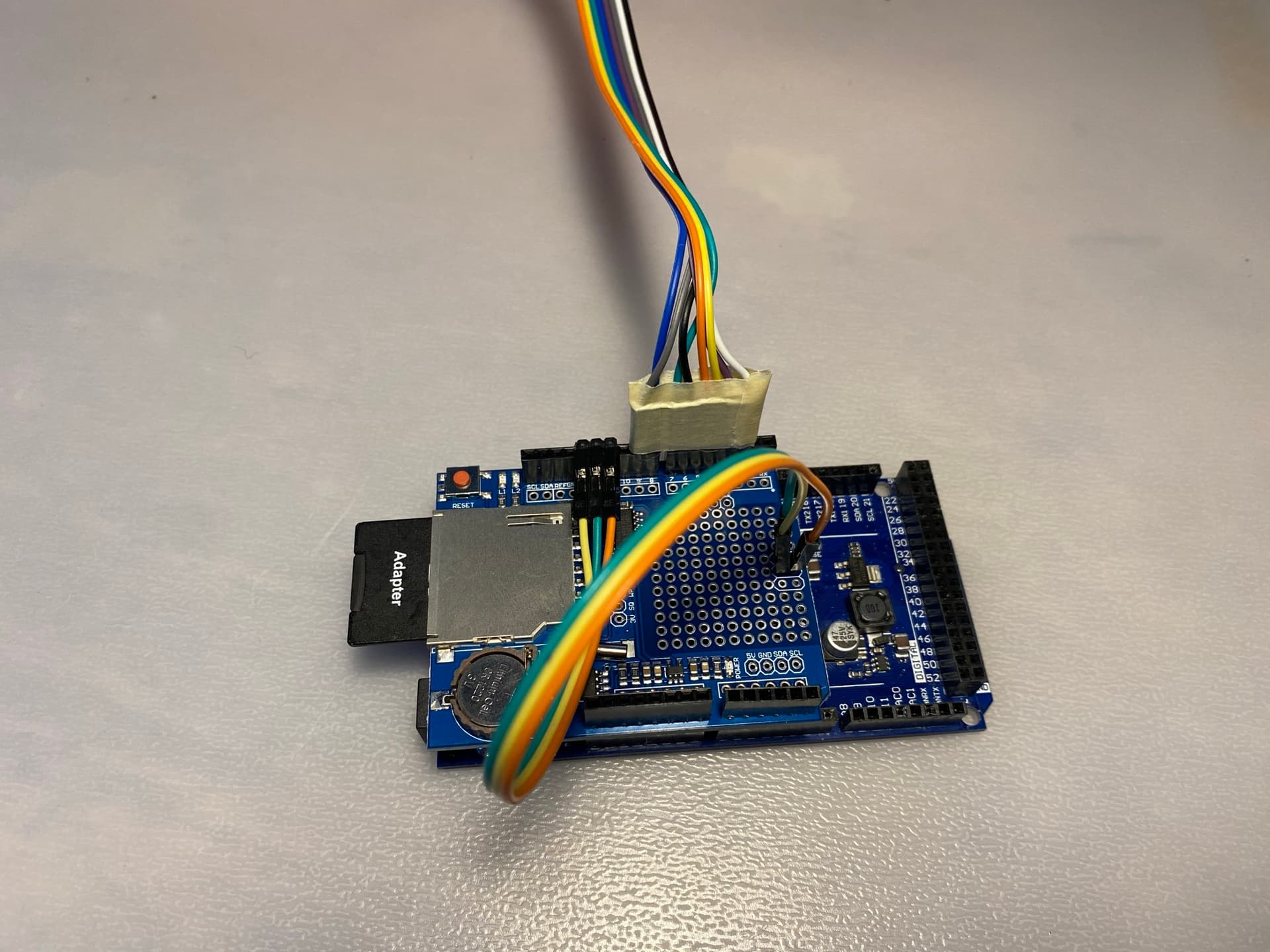
I am using: Arduino DUE, Data logging shield + SD, 4x4 Keypad (from a phone, but it seems to work fine). It will be a phone-like experience (I have an amp and speaker ready).
When I connect the keypad through a Data logging shield, pin no. 7 would stop receiving the input. That means only the first two columns of the keypad numbers are functioning (1, 2, 4, 5, 7..).
But all tests show that pin 7 is working fine (e.g. button-LED test).
EDIT: It seems that the problem is somewhere else: changing the input to other pins - same result with only two columns working.
This is how I connect DUE to Data shield: Adafruit Data Logging Shield with DUE ... everything's OK!!!
Keypad code I am using to test: https://arduinogetstarted.com/tutorials/arduino-keypad
If I unplug all SPI pins from the shield - the input works sometimes. Very weird. I have tried with multiple shields and Arduinos - same result.
Please show a complete schematic with all 3 components.
You need 8 wires for the keypad so there is info missing from this question.
Sounds like your pin assignments might be overlapping.
In the code before I am not accessing the data logger shield. Just connecting through it. So that's why I suspect it's something to do with the hardware.
No, at this point I want to test the keypad only. I've tested the data logger-SD with a separate code - all worked fine.
Pin headers were already attached- I've tested with the multimeter - seemed all good.
My suspicion is Shield ISP somehow clashes with the input pins (very weird).
I get your desire for developing one piece at a time, it's a good plan.
The reason I'm asking is because I'm curious if it's doing something since it's being powered, and all those pins are just floating. This is undesirable.
In this case I would investigate by adding the code to use the logger. That doesn't mean that you have to use it but I think you should create all of the variables and all of the setup for the logger.
There are jumpers from the ICSP to pins 11-13, but what about the existing pins? There's a thread about it linked in the first post, but a lengthy read. But I would worry about what is connected to pin 7 on the shield.
Good suggestions! I just checked the thread - I thought we found the solution! BUT...No.
I've bend 11-13 pins to be disconnected from DUE - same result.
When connecting the keypad to DUE in any of the ways without the Data shield - works perfectly!
EDIT:
OK, I just connected the keypad to pins 38-52 (even numbers only). Works fine! I can stick with that
But another problem - I cannot see the SD card anymore (Damn, I hate this shield). It seems the problem might be with Chip Select pin 10. But even after resetting it to HIGH and LOW (or how you do chipselect reset?) - the same result. I have reinserted the 11-13 pins to DUE btw
EDIT. Solved the issue of 10 pin not being chip select: