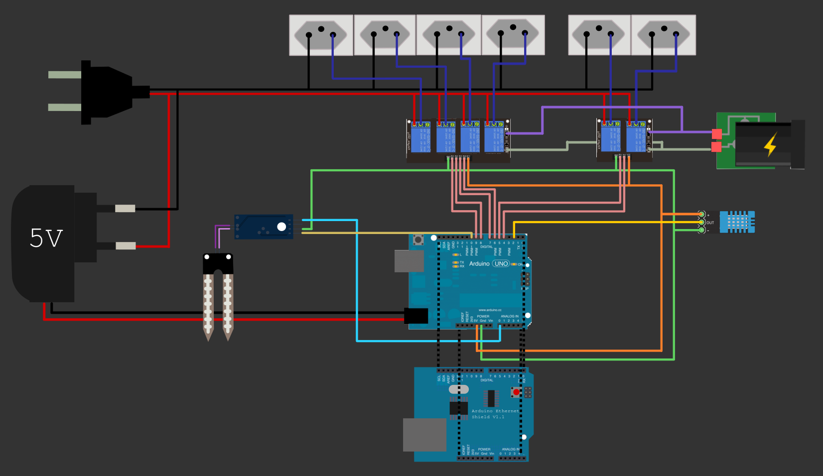
Can someone help me with this draw for my system controller online of garden?
I had already burned 1 shield and dont know what can be wrong D:
Can this connections burn my ethernet shield? Is something wrong?
What should i know to build a system like that?
Thank you!
There is no ethernet shield or power supply in your Fritzing.
The six 5volt relays alone could draw 6 * 80mA = 480mA. Add an ethernet shield, an Uno, and some sensors to it, and you could be way over the current limit of the onboard 5volt regulator.
Before we go any further, I suggest you post links to the parts you intend to use.
Leo..
Uno, sensors, and ethernet shield could be powered with a 5volt/1Amp USB charger, connected to the USB socket of the Uno. The Uno + sensors + ethernet will draw ~250-300mA.
Six relays (480mA) will push current over the limit of the onboard polyfuse.
I think you should use a different relay board.
This one has opto couplers, but no opto isolation.
Power the relays with a different (5volt/1Amp) supply.
Then you don't overload the Arduino, and you can have an extra safety layer (opto isolation).
2, 4, or 8-relay boards with a JD-VCC jumper are suitable.
Post a link here before you order.
Leo..
paulap:
I have an 4-relay board with JD-VCC, i can use it.
aren't opto coupler and opto isolation the same?
Yes, but post a link if you can. Or a clear picture.
No. Opto coupler is the actual part.
And you only have opto isolation if it's connected right.
For opto isolation, two separate 5volt supplies are needed. One for the Arduino and one for the relay board.
Remove the JD-VCC jumper.
Relay supply connects to JD-VCC (not VCC) and GND (ground) of the relay board.
Arduino's 5volt pin connects to VCC of the relay board. And the four inputs to Arduino outputs.
And finally, Arduino ground should NOT be connected to relay board ground.
If you do so, you will loose opto isolation.
Need more info and full code (use code tags) to answer the data logging question.
Leo..
if (client.connect("192.168.2.3",80)) { // Substitua pelo endereco de seu servidor
            delay(500);

           data = "temp1=" + String(t) + "&hum1=" + String(h) + "&humsol1=" + String(val) + "&vasoid=" + String(vasoid);


		client.println("POST /weeduino/add.php HTTP/1.1");
		client.println("Host: 192.168.2.3"); // Substitua pelo endereco de seu servidor
		client.println("Content-Type: application/x-www-form-urlencoded");
		client.print("Content-Length: ");
		client.println(data.length());
		client.println();
		client.print(data);
        }

	if (client.connected()) {
		client.stop();	// DISCONNECT FROM THE SERVER
                delay(1000);
	}
Just wondering why you need to switch 110/220 Vac. Most garden watering valves operate on 24 Vac - much safer in possibly wet conditions!
I think you do need the ground of the relay board to be connected to the Arduino board gnd but those Fritzing diagrams are always confusing. A proper schematic is much clearer.
FYI,
the standard procedure is to list the power supply rated current and below that the components and right next to each item, the rated current for that part and at the bottom , add them all up to arrive at the total power consumption for the components running off the same power supply. At the bottom you subtract the total consumed from the total supplied. It's simple arithmetic.