Hi,
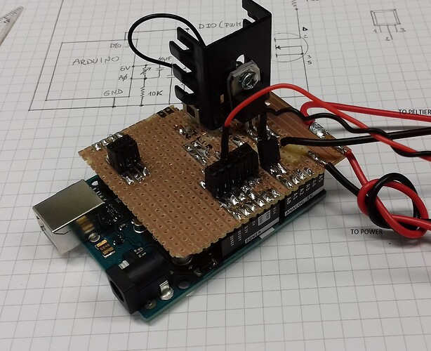
I am an Arduino beginner and I realized a circuit to pilot a peltier cell using a n-channel mosfet and monitor the temperature with an NTC.
A crude schematic is attached.
The circuit is soldered to a development board that sits on the Arduino ports (like a shield would do).
As a test, and to avoid draining high currents, I tried the circuit with a resistor 10kOhm instead of the peltier and everything worked fine: I use the analogWrite function to change the PWM pin duty cycle (pin ~3 in the schematic) and see a corresponding change in the voltage on the resistor.
But...
If I try to drive the peltier, which drains up to 2A, I almost immediately lose connection with the Arduino and must reset it (disconnect power and reconnect it).
This happens consistently if I send the "peltRamp" command over the serial monitor (see code below): it works fine with the resistor but crashes the Arduino if the peltier is connected.
I suspect it might be a problem in the faast switching of high currents but could not find any mention of it in the forums. Is anyone able to shed some light on this? I would be really grateful.
#include <SerialCommand.h>
#include <math.h>

SerialCommand sCmd;

// PELTIER VARIABLES
int peltier= 3; //The N-Channel MOSFET is on pin 3
int peltPwr= 0; //Power level to the peltier (0-99%). Start with 0.
int peltier_level = map(peltPwr, 0, 99, 0, 255); //This is a value from 0 to 255 that actually controls the MOSFET
int rampSpeed= 10; //10% per second

// NTC VARIABLES
int tempPin= A0;
float Vout;
float Raux=10000;
float Rout;  // [ohm]  Current NTC resistance
float beta=4235;  // [ohm] Rinf parameter
float Rinf= 0.013558; //[ohm] Rin parameter
float tempC;
float tempK;
float Vin;

/////////////////////////////////////////////////////////////
void setup() {
  // put your setup code here, to run once:
  Serial.begin(9600);
  //Serial commands
  sCmd.addCommand("*idn?", sendId);
  sCmd.addCommand("ramp", peltRamp);
  sCmd.addCommand("pwr?", peltRead);
  sCmd.addCommand("peltON", peltON);
  sCmd.addCommand("peltOFF", peltOFF);
  sCmd.addCommand("+pwr", peltIncrease);
  sCmd.addCommand("-pwr", peltDecrease);
  sCmd.addCommand("temp?", readTemp);
}

/////////////////////////////////////////////////////////////
void sendId(){
  Serial.println("PELTIER CONTROLLER");
}

/////////////////////////////////////////////////////////////
void peltRamp(){
  //RAMP THE POWER TO THE SPECIFIED VALUE
  char *arg;
  int newPwr= atoi(sCmd.next());

  if (newPwr <0) newPwr=0;
  if (newPwr >99) newPwr=99;

  int delta= newPwr - peltPwr;
  float nSteps= 2*abs(delta)/rampSpeed;

  for (int i=0; i < nSteps; i++){
      peltPwr= peltPwr + (delta/abs(delta))*rampSpeed/2;
      peltier_level = map(peltPwr, 0, 99, 0, 255);
      analogWrite(peltier, peltier_level); //Write this new value out to the port
      peltRead();
      delay(500);
  }
  peltPwr= newPwr;
  peltier_level = map(peltPwr, 0, 99, 0, 255);
  analogWrite(peltier, peltier_level); //Write this new value out to the port
  peltRead();
}

/////////////////////////////////////////////////////////////
void peltRead(){
  //RETURN THE CURRENT POWER LEVEL
  Serial.print("Power %: ");
  Serial.println(peltPwr);
}

/////////////////////////////////////////////////////////////
void peltON(){
  //SET THE CHANNEL ON (FULL POWER)
  peltPwr= 99;
  peltier_level = map(peltPwr, 0, 99, 0, 255);
  analogWrite(peltier, peltier_level); //Write this new value out to the port
  peltRead();
}

/////////////////////////////////////////////////////////////
void peltOFF(){
  //SET THE CHANNEL OFF (NO POWER)
  peltPwr= 0;
  peltier_level = map(peltPwr, 0, 99, 0, 255);
  analogWrite(peltier, peltier_level); //Write this new value out to the port
  peltRead();
}

/////////////////////////////////////////////////////////////
void peltIncrease(){
  //INCREASE POWER BY 10%
  peltPwr= peltPwr +10;
  if (peltPwr>99) peltPwr= 99;
  peltier_level = map(peltPwr, 0, 99, 0, 255);
  analogWrite(peltier, peltier_level); //Write this new value out to the port
  peltRead();
}

/////////////////////////////////////////////////////////////
void peltDecrease(){
  //DeCREASE POWER BY 10%
  peltPwr= peltPwr -10;
  if (peltPwr<0) peltPwr= 0;
  peltier_level = map(peltPwr, 0, 99, 0, 255);
  analogWrite(peltier, peltier_level); //Write this new value out to the port
  peltRead();
}

/////////////////////////////////////////////////////////////
long readVcc(){
  //Read 1.1V ref against AVcc
  //set the reference to Vcc and the measurement to the internal 1.1V ref

  ADMUX= _BV(MUX3) | _BV(MUX2);
  delay(2); //Wait for Vref to settle
  ADCSRA |= _BV(ADSC); //Start conversion
  while (bit_is_set(ADCSRA,ADSC));
  uint8_t low = ADCL;
  uint8_t high = ADCH;

  long result = (high<<8) | low;

  result = 1125.3L / result; //Caltulate Vcc in V; 1125.3 = 1.1*1023
  return result; // Vcc in mV
}

/////////////////////////////////////////////////////////////
void readTemp(){
  Serial.print("Temperature (C): ");
  Vout  = 0;
  Vin = readVcc();
  for(int i=0; i<15; i++)
  {
    Vout += Vin*((float)(analogRead(tempPin))/1023.0);
    //sample+= analogRead(tempPin); //read the value from sensor
    delay(3);
  }
  Vout = Vout/15;
  Rout= (Raux*(Vin - Vout)/(Vout));
  //Temp calculation
  tempC= (beta/log(Rout/Rinf))-273.15;
  Serial.println(tempC);
}

/////////////////////////////////////////////////////////////
void loop() {
  // put your main code here, to run repeatedly:
  sCmd.readSerial();
}
PeltierSchematic.pdf (89.2 KB)
