Arduino + L298n H Bridge Driver = Low Voltage Output

Hello!
Could anyone please help me find where is the problem ?
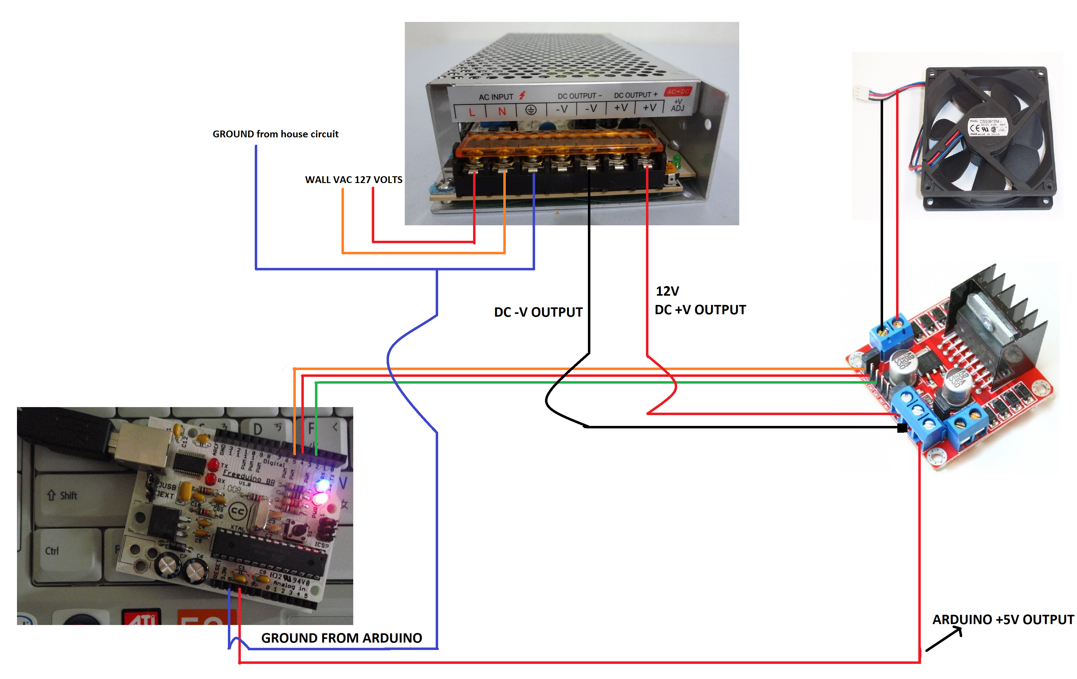
I did some photos and one video of the circuit to help and make it easier to find it out.

The objetive is simple: control via PWM (Arduino->L298n) a 12V motor fan.
It seems i'm having problem with ground. But i have tried all possible combinations and none went fine.
I do already checked the 12v font supply and it's fine, also the 5v (from arduino to the l298n driver) is fine too.

My arduino model is Freeduino - Freeduino is a collaborative open-source project to replicate and publish Arduino-compatible hardware files. - http://www.freeduino.org/freeduino_open_designs.html

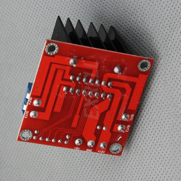
Motor Driver 2A Dual L298 H-Bridge: Motor Driver 2A Dual L298 H-Bridge [L298N] - US $4.00 : HAOYU Electronics : Make Engineers Job Easier

My code:

#define ENA 5 //enable A on pin 5 (needs to be a pwm pin)
#define IN1 2 //IN1 on pin 2 conrtols one side of bridge A
#define IN2 4 //IN2 on pin 4 controls other side of A

void setup()
{
//set all of the outputs
pinMode(ENA, OUTPUT);
pinMode(IN1, OUTPUT);
pinMode(IN2, OUTPUT);

}

void loop()
{
int duty=255;

//setting IN1 high connects motor lead 1 to +voltage
digitalWrite(IN1, HIGH);

//setting IN2 low connects motor lead 2 to ground
digitalWrite(IN2, LOW);

//use pwm to control motor speed through enable pin
analogWrite(ENA, duty);

}

The problem is no matter what i do i never get an output of more than 5V. I tried to make an variation of this main scheme and i got 2V but when i touch with my hands in the metal parts of ARDUINO it goes up to 3.5 or 4 Volts..

All photos and video can be found here: Dropbox - Error - Simplify your life

The circuit that is stable and have low output is that one:

the variation that have voltage variations when i touch it witg my hands is that one:

I have recorded a video of tha circuit too, as you can find here:

Does anyone have any idea?
Thank you!

That 3MB file is waaaaaaaaaaaaaaaaaay too big to expect anyone to view. In the sticky at the top of the forum it says:

Please resize photos down to a reasonable size. A 4 megabyte photo takes a long time to download. As a courtesy to other forum users, images should be no more than a couple of hundred K bytes.

When we post code we use code tags, your code !!

You should ground the motor shield with the arduino .. Common ground !!!

Low voltage output ? Where exactly ? And how low is it ?

JimboZA , you are right. sorry for that.
here is the 2 circuits versions attached in jpg and smaller size.

also thinnk the dropbox folder link is better to see all them in thumbnails, because of the video too..

zaxarias, we get a maximum of 3 Volts. When i share the grounds: ARDUINO + DRIVER i get inconstant voltage flow about +- 2 Volts.. then if i touch some metal part of the arduino it goes UP.
You can see the voltage output photo here:

Sorry for the code with no tags, here is the code in tags:
My code:

#define ENA 5  //enable A on pin 5 (needs to be a pwm pin)
#define IN1 2  //IN1 on pin 2 conrtols one side of bridge A
#define IN2 4  //IN2 on pin 4 controls other side of A

void setup()
{
  //set all of the outputs
  pinMode(ENA, OUTPUT);
  pinMode(IN1, OUTPUT);
  pinMode(IN2, OUTPUT);

}

void loop()
{
int duty=255;

      //setting IN1 high connects motor lead 1 to +voltage
      digitalWrite(IN1, HIGH);   
      
      //setting IN2 low connects motor lead 2 to ground
      digitalWrite(IN2, LOW);  
      
      //use pwm to control motor speed through enable pin
      analogWrite(ENA, duty);  

}

thank you!!!

I didn't look at your code but i don't think it's responsible for that low voltage..
You re doing something wrong at the wiring.. The second image attached on your last post looks fine , that's how they should be wired !!!

Hi zaxarias,
unfortunally if i make in this way the voltage becomes instable, and if i touch in some metal part it goes up.. typical an ground problem..

if the driver is lot supplied with -Vcc from the 12v supply it does not turn on so if i put the ground there sharing ground (from supply + ground arduino) with the -Vcc from the 12 power supply it becomes instable...

I think we have a problem here of how to join the -Vcc with the ground and arduino ground. Got now ?
See the 12v power supply is that one: http://img.clasf.com.br/2014/04/13/Fonte-Chaveada-12v-10a-120w-Cftv-Fita-Led-Som-bi-volt-Autom-20140413230851.jpg and it has:
127Vac input + Ground
2x - DC OUTPUT
2x + DC OUTPUT

Maybe the question is.. we have to use this power supply ground into arduino ground ? also how about the -DC OUTPUT ? there is a logic to join them together in the driver GROUND input ?

.. than you so much for your attention!

You should jumper the power supply -Vcc pins together and the +Vcc pins together.

raschemmel hello. Thank you. But i didn't understand.. could you please explain a little better about the jumpers? I cant figure it out... thank you so much!

STOP !!!

check the bottom of the board !! screw terminal voltages should be printed on the bottom.

check to see if 12 volt is on the outside, near the corner.

disconnect the 5 volt from the board, that 5 volt connection is an OUTPUT !

and turn that photo around the correct way, you have it flopped in the picture.

http://www.ebay.com/itm/L298N-DC-Stepper-Motor-Driver-Controller-Module-Robot-Dual-H-Bridge-For-Arduino-/370966436323?pt=LH_DefaultDomain_0&hash=item565f5299e3

ebay, open this page and scroll way down

Dave has a point. Are there two DIFFERENT VOLTAGES on that supply ? I can't see any voltage labels.

this is on every e-bay page for that driver board.

Notes:
This module has a built-in 5v power supply, when the driving voltage is 7v-35v, this supply is suitable for power supply, DO NOT input voltage to +5v supply interface, however ledding out 5v for external use is available.

raschemmel:
Dave has a point. Are there two DIFFERENT VOLTAGES on that supply ? I can't see any voltage labels.

Dave's right . If you connected it that way you connected the arduino 5V regulator output with the L268 onboard 5V regulator output. If you're lucky they both went into shutdown mode and there was no damage. Check the labels on the power supply.
Why does it have TWO V- and TWO V+ are both for the same voltage or is one of them 5V ?

Ha ha ha. Funny, Dave. Do you have x-ray vision ?

raschemmel:
Ha ha ha. Funny, Dave. Do you have x-ray vision ?

no, that's why I use those glasses. !

gosh, how could any boy grow up in the States and not buy a pair to see through girls clothes ?

here is a alteration of your layout.

eliminated the 5v connection form your arduino (leads were wrong on the arduino, the 5V is closer to the board edge and the GND is near the center.

since you are only turning the fan on an off, and not reverse, I think you only need 1 connection. the h-bridge is only ever used one way. the 3rd wire is not needed as you do not show anything connected to the second h-bridge. if the fan is running in reverse, either move the pin over one or swap the wires to the motor.

as a note, I think you can remove the jumper that is behind the power input screw terminals and not use the on-board voltage regulator. like if you have 5 volts in for the motor, the on-board volt regulator would not be able to put out 5 volts. this is only my understanding of the L298 chip. I have not used that board.

gosh, how could any boy grow up in the States and not buy a pair to see through girls clothes ?

I grew up in California. I didn't need them because all you have to do is go to the beach in the summer...

I thought every day was summer in California ?

last I heard the weather station had to make a new recording, the old was was on tape and finally wore out.

Question about PWM with that chip.

Do you pwm the enable or do you pwm the signal and leave the jumper on the enable ?

Dave