Currently I am on a mission to fix a pet hate of mine, out of sync light LED lights in side my computer, I personally hate the proprietary plugs that have come with the fan units ive installed, forcing me to use the LED/PC Fan controller hub device, which has a couple buttons for speed of fan and lights colour but not overly useful,
The mission is: Have the motherboard output (Through is traditional LED output) into the arduio, where it is deciphered and transmitted to the Fans in-built LEDs, unfortunately the Motherboard outputs traditional 12v LED lights, and the fans built-in lights are Addressable LEDs, Then the fans shall simply work by passthrough on the board, no actual control or interaction with the Arduino circuitry just translate the proprietary plug (which is only a 8x2 plug with a pin missing) into standard fan header plugs and I'll plug them straight into the motherboards fan outputs.
So currently, I can get a normal arduino to drive addressable LEDs not an issue, I can read the outputs of the motherboard, although I havent tried the fan passthrough since its just connections I believe that wouldnt be an issue.
A lot of this work I have done, and developed its own PCB, and assembled the schematic attached, I am using a Serial to TTL converter board pre-assembled to drive the ATmega, and here is where the issue I am having is, every time I assemble this components I end up burning out the Serial chip, I plug it into power in within a minute the chip is smoking and then ruined. I cant figure out where I have gone wrong or whats shorting out, would someone be so kind as making some suggestions on the schematic and hopefully can work this out !
This is the USB to Serial Chip:
Please note the Jumper in J1 between the 5v lines of the output of the TTL is new, and havent tried that yet since I dont have an alternate 5v source, but the final design will have 5v supplied off the PC
Powersupply
I plug it into power in within a minute the chip is smoking and then ruined.
Clearly you are doing something wrong. However it is hard to say what because if the lack of detailed information. OK on the schematic but how does this connect with the serial adaptor? Can you post the wiring of the connector header to the adaptor as well as posting a picture.
I would start by checking to see if there is any shirts to the supply or ground on the data lines, then check the auto reset circuit.
I would check that the adapter sends TTL by viewing the signal on a scope. Check all the voltages on the header to your PCB as well.
Hello again Grumpy, sorry for the substantial dely in responding.
Here is a photo of the board and associated part, at the time I had a preprogreemed chip in the socket, however have since after frying the adaptor removed it just incase, which reminds me I should check to see if that still works haha.
The Adaptor was just straight up soldered through PIN holes on the board,
I cant seem to find any stray grounding issues or shorts through using multimeter, unfortunatly I also dont have a scope avalible to use
Hey Tom, good point on popping the chip and trying DMM, I will add that to my troubleshoot ideas. Have yet to still get it back to the bench.. working all the time definitely doesnt help my projects.
Understand the pinout in the schematic doesnt match the Arduino chip, but they are correctly laid out.. it was an issue with the schematic program I was using, unfamiliar with it .. but yeah is correct..
First prototype board I got, burnt up the ft232r every time I would plug them in -
Now the second prototype board, doesnt burn up the ft232r chips straight away but will if being left there for a while.. however it still wont talk to the arduino..
This is now my third attempt at having a PCB fabricated, going to do all the routes on the PCB myself and directly as shown on the schematic, no nets or the like (except ground) see if then I can better diagnoise which element of the schematic is causing greif here -
Still have no idea why this is such a pain.. bare bones circuit with a ft232r .. and I cant seem to get them to work.. hmm.. havent even got to the point where its controlling LEDs or reading signals - such a pain!
Hi,
Did you trace out the major tracks with a DMM before placing any components?
Check if you do not have a short circuit between 5V and GND with DMM.
Did you power the PCB up with power applied via U_Power header and check the voltages at the supply pins on the 328 IC socket?
Do all these checks before adding components.
Can you post an EXPORTED image of your PCB pattern please?
TomGeorge:
Hi,
Did you trace out the major tracks with a DMM before placing any components?
Check if you do not have a short circuit between 5V and GND with DMM.
Did you power the PCB up with power applied via U_Power header and check the voltages at the supply pins on the 328 IC socket?
Do all these checks before adding components.
Can you post an EXPORTED image of your PCB pattern please?
Thanks.. Tom...
For the last board I did trace the tracks and they all appeared to be connected how I would expect them to be.. however still no such luck ! Also to awnser your question before about using a nano and essentially having a break out board - well yes I could do that indeed and probably wouldnt of had the headache to this point - but half of this is just doing it for the sake of the exercise ya know ? I should be able to make this work - so here I am trying for the third time haha -
Power was supplied through the FT232RL chip - the purpose of the U_Power header is so that I can remove the FT232RL chip later and the arduino can run off 5v supplier elsewhere, no intention to have them both simultaniously running. Also 5v read off my DMM everywhere it should of been - the Atmegas seem to also still work and function fine - put them into an arduino duo board and programed nativaly no problem.
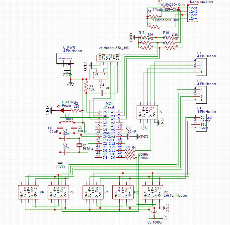
Here is the most recent schematic, and another board on the way - this time however I have segregated out the Arduino circuit and the break-out board bits, so unless I put the 1000uf cap in C7 the majority of the board should be seperated and therefore no shorts could or would occur somewhere...
The caps on the crystal on the last diagram are reduced to 22nF (were 100n).
That's still 1000 times too high. The crystal clock will never work with those values.
Try 22pF.
Leo..
Wawa:
The caps on the crystal on the last diagram are reduced to 22nF (were 100n).
That's still 1000 times too high. The crystal clock will never work with those values.
Try 22pF.
Leo..
I am not so great at making schematics or using the correct denomination oops - the caps I used and have in that position are indeed 22pF ones - 22J markings
Hi,
What fault does the last PCB have?
If all you plug in is the FTDI to the PCB with NO COMPONENTS fitted, what happens?
What happens if the 328 is not plugged in but all components are fitted?
Can you post a picture of the solder side of the PCB please?
Why have you got a L/C circuit between Vcc and AVcc, the UNO R3 doesn't do this, just connects them to the same 5V source.