I actually have a software background so my experience in electrical engineering is somewhat lacking. Never the less, I have given my first Arduino project a go and for the most part I am quite happy. However I feel as though there could be a vast amount of improvement that can be achieved regarding the load cell readings.
I am building a digital scale that weighs a maximum of 40Kg. At the push of a button, the scale outputs the current weight to a pc connected via USB. Everything is working quite well except I am getting a lot of bounce when reading the analog input from the loadcells.
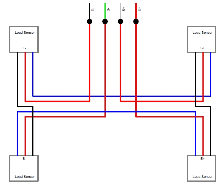
I have 4x 50kg 3-wire loadcells (the ones typically found in bathroom scales – similar to these https://www.sparkfun.com/products/10245 - my wires were different colors, blue, black, red) wired in the configuration below:
I am using an INA125P to amplify the signal to my Arduino as per the diagram below:
I have a regulated 9v dc external supply powering the entire system.
I am using a booster to increase the voltage to 10V to the load cells as that is the specified excitation voltage. I am also using this 10V supply to the INA125P
I have modified a USB cable such that it is a data-only cable by removing the voltage line, so that when the power supply is turned off the entire system turns off and is not powered by the connected USB.
I have basically followed a bunch of online articles, pulled apart a scale, read a bunch of tutorials, a bit of trial and error and came to the above arrangement. This much I was able to do on my own. I have smoothed out the analog readings dramatically on the software end by using a running median combined with an averaging function but still get to much bouncing.
There are loads of articles online that are very helpful in showing exactly how to create a scale using an Arduino and the INA125P, but I was unable to find one that clearly demonstrated how to apply a negative voltage to the INA125P. I recall reading somewhere that I should be able to achieve better resolution by applying a negative voltage to the INA125P but struggled to understand how it was done and now I can’t seem to find where I read it to begin with. Even if I somehow worked out how to create the negative voltage and then worked out how to apply it to the INA125P and managed to use the entire 10-bits of the Arduino’s built in ADC to get a resolution of 1023 I still feel as though the bounce I am experiencing is unusually high, especially on the lower end of the weight (I get almost 200 grams of swing when weighing an object that weighs 400 grams).
After a lot of tinkering and testing I discovered the following unusual behavior…
The voltage at A0 varies slightly when I change the USB from one pc to another (even such that the usb cable’s voltage line is removed) and as a result the reading on the scale changes slightly from one pc to another.
The voltage at A0 increases if the PC connected to the USB has the Arduino Leonardo drivers installed (so it is not just connected as a HID device).
I should note that…
Changing the USB from PC to PC shows no change to the excitation voltage or the voltage supplied to the INA125P from the buck booster.
Changing the USB from PC to PC shows no change to the voltage at Aref or at Vin.
I was hoping that I could get the answers to the following questions.
How can I modify my circuit so as to reduce the bouncing and stabilize the analog signal from the INA125P at A0?
How do I create the required negative voltage and how do I then apply it to my circuit such that I am able to achieve the full 10bits of resolution?
How do I stop the voltage variation at A0 when connected via USB to different PC’s?
I'm not a specialist with signal amplification but the circuit wiring on this page Load Cell Amplifier makes more sense to me than your wiring. Have you tried that one?
From what I can tell, the only difference in the way the wiring that article shows is that he is using two batteries to supply the ina125p. One to supply the positive voltage and then he inverts the other to supply the negative voltage.
I am not using batteries and would like to stick with my current ac to dc power supply.
Do you think that I could somehow split the voltage from my buck booster to provide both a negative and positive voltage?
From what I can tell, the only difference in the way the wiring that article shows is that he is using two batteries to supply the ina125p. One to supply the positive voltage and then he inverts the other to supply the negative voltage.
I see another difference: You connected E+ to your positive voltage while the article connects it to 4/15. You connected that to the Arduino AREF. This gives you a stable reference voltage for the ADC but an unstable for the load cell. The load cell is probably much more sensible to instable voltages than the ADC is. What do you think?
Sorry, I did notice that and I should have elaborated. My load cells specify an excitation of 10V hence the reason why they are being supplied by the 10Vdc supply. I should mention that the 10V supply is regulated and upon measurement with a multimeter I do not notice any fluctuations... it seems quite stable.
Is there perhaps a way I can test this more definitively?
I believe I was able to supply -10V to the V- pin on the INA125P using a voltage converter IC ( ICL7660A ) in conjunction with two 10uF capacitors as per the circuit below.
However, I have not noticed any change in the results of the analog readings... I'm still getting the same range of around 300 to 1023. I had the impression with a negative supply at V- pin I would be able to get the full 0 - 1023 range.
I should mention that the 10V supply is regulated and upon measurement with a multimeter I do not notice any fluctuations... it seems quite stable.
You won't see fluctuations on the multimeter because it's not fast enough. Check it with a scope or use a voltage divider and an appropriate Arduino sketch to see if the voltage is really constant.
What regulator do you use? The datasheet usually tells you how much ripple it leaves. The ICL7660A will introduce additional ripple as you can see in the datasheet figure 14.
Ok, because I don't have access to a scope, and noticed that the specs for the buck booster I am using says that the output ripple is 50mV, I thought it would be easier to just change up my circuit so that I completely bypass the buck booster 10V supply and supply my load cells with 5V excitation from the Vref5 pin of the ina125p so as to get a more stable voltage.
I obviously had to re-adjust Rgain, however the lower excitation voltage of 5V still seemed to work even though the spec for the load cells says excitation 10V. That said I am getting virtually the exact same level of fluctuations, so unfortunately not much improvement, if any.
I am still confused as to why I am not getting a better ADC range when supplying the INA125P with the negative voltage though...
I am also still getting that weird behaviour where the reading at A0 is effected by the Arduino being plugged into the USB port.
I just stumbled across what might be the solution to my problem. When I was fiddling around with the USB cable I found the scale readings would jump around a lot.
I changed to the usb cable to a better quality USB cable and the readings stabilized some what. I added a ferrite bead to the cable and they stabilized some more. There appears to no longer be any difference between my readings from PC to PC.
Is there anyway to completely eliminate the noise that is generated by the USB cable??