I corrected the pins needed for the connection between the Mega and the LoRa but it still shows me "LoRa Radio init failed". I'm using the Radiohead Library specifically the RH_RF95.h in my IDE.
Tried with an Arduino Uno and it all works perfectly fine.
srnet
September 30, 2023, 8:02am
2
Did you use logic level conversion components between the Mega and the LoRa module ?
hello I used AMS1117-3.3V Power Supply Module Voltage Regulator as my step down voltage regulator but it still dooesn't work.
J-M-L
September 30, 2023, 8:22am
4
did you read the caution #1 ?
Your MEGA is a 5V device...
how did you wire the SS SCK MOSI and MISO pins?
srnet
September 30, 2023, 8:22am
5
If you connected the 5V logic level signals of the Mega to the LoRa device, you could have damadged the LoRa device since it needs 3.3V logic signals.
Study the text of the Sketch you posted;
"CAUTION: you must use a 3.3V type Arduino".
Much easier to use LoRa devices with 3.3V Arduinos.
I used this AMS1117-3.3V Power Supply Module Voltage Regulator . I wired to SS to D53, SCK to 52, MOSI to 51, and MISO to 50.
I didn't, I've been using the AMS1117 for it. I need to use the Mega since I have multiple sensors and relays for the project.
srnet
October 1, 2023, 6:56am
8
Thats just the power supply the LoRa device.
You still need to use logic level conversion circuits between the Mega and the LoRa device on the SCK, MOSI, MISO, SS and DIO0 pins.
J-M-L
October 1, 2023, 7:16am
9
That’s not good. When one of the pin from the mega goes HIGH it « sends » 5V to the matching pin on the module which only accepts 3.3V
If you are unlucky your module is now dead…
I see, this is noted. However, why does it work on my Arduino UNO and not on my MEGA?
I see. Should I use more AMS1117s for all the pins stated?
srnet
October 1, 2023, 7:36am
12
Nope.
For some details do a Google search on;
'Arduino Logic Level Conversion'
J-M-L
October 1, 2023, 7:39am
13
There is a bit of slack and the pin can possibly take some abuse for some time
I would not recommend testing again on the UNO because if the module is not dead you might kill it.
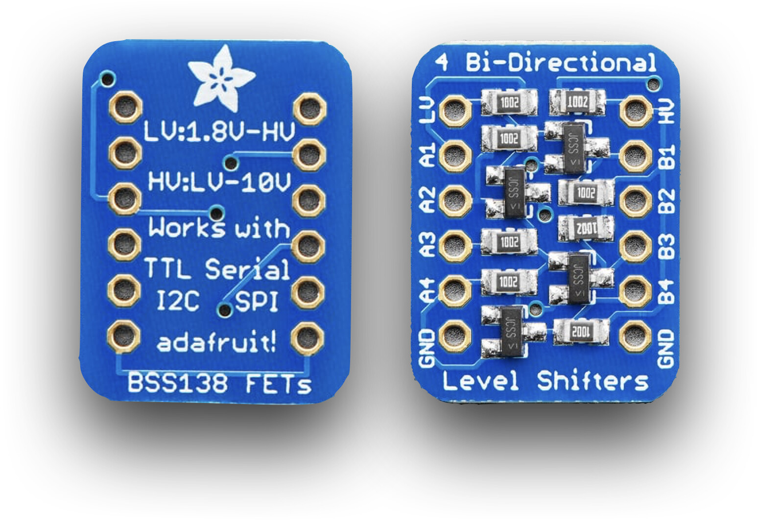
Get a voltage adapter board and use it to translate the signals -something like 4-channel I2C-safe Bi-directional Logic Level Converter [BSS138] : ID 757 : $3.95 : Adafruit Industries, Unique & fun DIY electronics and kits
Thank you for this! Question, should I also use this for the RST and DIO0 pins?
J-M-L
October 1, 2023, 8:00am
15
the thinking should be:
if the pins are input to the module then you need to adjust the voltage they "receive" to the spec.
if the pins are output of the module, then when they are set HIGH they are set to 3.3V which will be seen as HIGH on the other side by the MEGA (3.3V is not 5V but still high enough to be seen as HIGH)
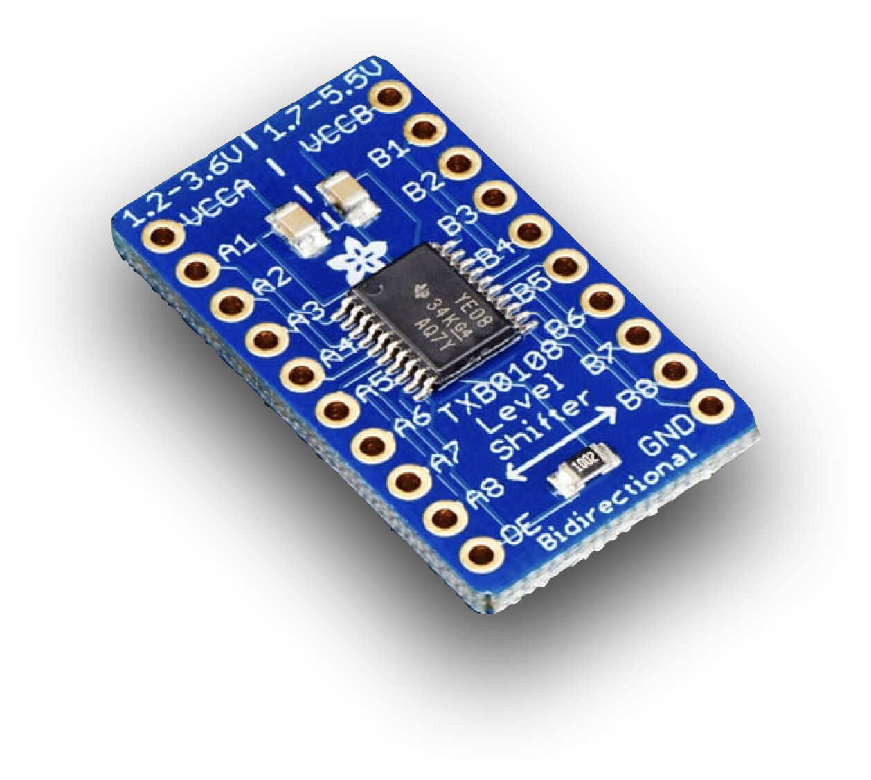
if you need to shift more pins, there are 8 way modules like 8-channel Bi-directional Logic Level Converter [TXB0108] : ID 395 : $7.95 : Adafruit Industries, Unique & fun DIY electronics and kits
did a search and thank you for this! just ordered one and hoping all goes well once it arrives. again, thank you!
right! this is noted and thanks a lot.
thank you! will be updating once it arrives. It's for a thesis project and thank you for the big help!
Hello, update regarding this.
The TXB0108 arrived however, it still doesn't work.
Wired it like this
LORA------LLC------MEGA
3V3---VCCA--VCCB-----5V
The gnd of the LoRa is connected to the Mega.
Any idea how this doesn't seem to still work?