Arduino mega standalone crystal issue

Hi

I hope someone can help me, im having a clock issue with a standalone mega that im making to control a TLC5947, bootloading and programming are fine incase you wanted to see the code.

#include <Wire.h>
#include "Adafruit_TLC5947.h"

#define NUM_TLC5974 1
#define data    8
#define clock   9
#define latch   7
#define oe  6
#define eeprom 0x50

Adafruit_TLC5947 tlc = Adafruit_TLC5947(NUM_TLC5974, clock, data, latch);
void setup() {  // initialize digital pin 13 as an output.
  Serial.begin(115200);
   pinMode(oe, OUTPUT);
    tlc.begin();
  tlc.setLED(0, 0, 0, 0);
  tlc.write();
}
void loop() {

digitalWrite(oe, LOW);
   tlc.setLED(0, 1000, 0, 0);
  tlc.write();
  Serial.println("RED");
  delay(500);
 tlc.setLED(0, 0, 0, 0);
  tlc.write();
  digitalWrite(oe, HIGH);
  Serial.println("OFF");
 delay(500);
 digitalWrite(oe, LOW);
   tlc.setLED(0, 0, 1000, 0);
  tlc.write();
  Serial.println("GREEN");
  delay(500);
 tlc.setLED(0, 0, 0, 0);
  tlc.write();
   digitalWrite(oe, HIGH);
   Serial.println("OFF");
 delay(500);
 digitalWrite(oe, LOW);
   tlc.setLED(0, 0, 0, 1000);
  tlc.write();
  Serial.println("BLUE");
  delay(500);
 tlc.setLED(0, 0, 0, 0);
  tlc.write();
   digitalWrite(oe, HIGH);
   Serial.println("OFF");
 delay(500);
}

my above code is simple and i have tried it on an actual arduino mega which works fine. what happens is the sequecnes are off and somtimes the wrong led lights up, this is why i believe it is a crystal issue when using a scope the mhz frequency changes drops from 16 down to 15 and back up.

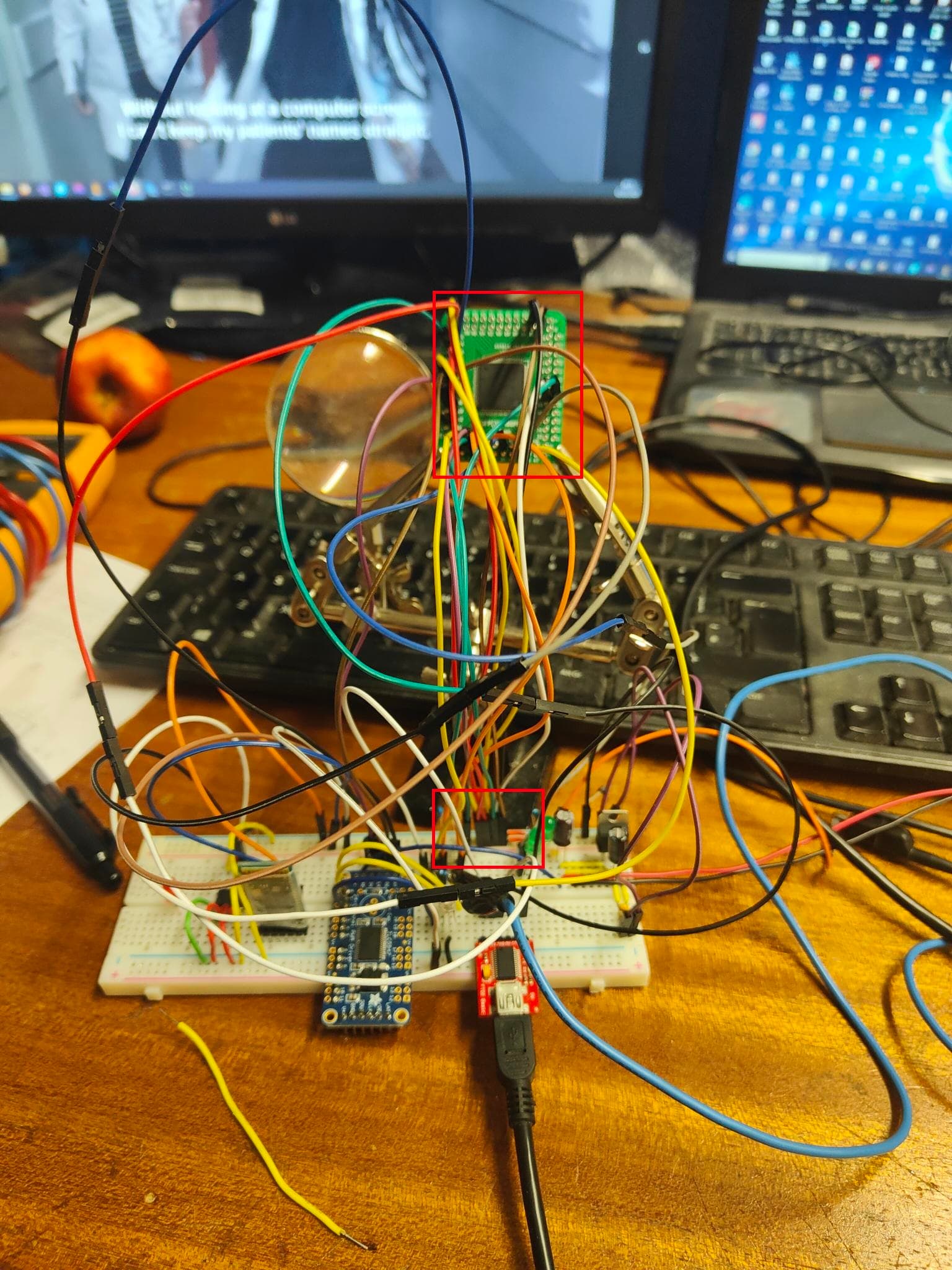
currently the whole project is on a breadboard with a TQFP100 breakout board it is shown on image 1 and i wanted to double-check if this is what is causing the issue as the crystal is far away from the IC and connected by two long wires.

Im not sure if it's the issue but i believe it is, so i wanted to double-check if it is not an issue i have attached a schematic and a board layout on how it should work it is also how it is layed out on the breadboard, hoping someone can help


Thank you

That is likely to cause problems. The crystal, and the associated capacitors, should have the shortest practical connections.
This is one I did for 328p

What is this? I don't see it anywhere in your picture.

Hi

Thats the mega2560 IC connected by a 16Mhz crystal with 2 x 22pf capcitors and a 1M ohm resistor the 1M is there as i wasnt sure if it is needed, i wanted to know if that distance is perfect to have or should it be closer. if you are trying to reference it on the image with the breadboard it is behind a bunch of wires far from the IC

Thank you

The distance in the layout you show should be fine but as I said I don't see that layout in your picture. Exactly what are you trying to show here, how it should be or how it actually is?

Hi

i havent developed the PCB yet so im still designing it, so i wanted to show and ask if that distance is ok for when i do fabricate it, sorry i should have said that when creating the post at the start

below is a picture of where the crystal is compared to the IC on the breadboard the one below is where the crystal is located, behind the wires the IC is at the top

Thank you

Yes, the distance is fine. As for you breadboard set-up I'm suprised that it does anything at all with that big rats nest of jumpers.
You need to place all the modules on a breadboard and you short wires for connections, NOT those long jumpers.

Like this:
Nice and neat

1 Like

Hi

thank you for that, honestly im surprised i got it to work as well i got it to bootload and even upload the blink sketch even though the timing was off with the blinks due to the crystal issue. i brought a cheap breakout board for the tqfp100 which i couldnt fit on the breadboard so did my best, but im sure it will be fine when i fabricate the pcb.

Damn now that is nice neat :slightly_smiling_face:

thank you

hi

im hoping you might be able to help me with something else i found this guide
https://www.instructables.com/ATMEGA2560-Standalone-Using-Arduino-UNO/

i followed it and now i have only pin 10 connected to 5v and pin 11 to gnd no other pwr connections and i have connected the 16mhz and the 2 x 22pf caps to the actual board at the back so its right next to it and now if i remove the gnd connection to the 22pf caps the ic still works, have i done something wrong

No sure what you are asking.
The load capacitance of the crystal is listed in th data sheet.
This explains how to calculate the two capacitor values.

Did you change the fuse settings from the factory default?
From here

Hi

since i used nick gammon bootloader these re the settings i have for the fuses
LFuse = 0xFF
HFuse = 0xD8
EFuse = 0xFD
Lock byte = 0xEF
Clock calibration = 0x8B

Looks like you have external crystal selected as required.

This topic was automatically closed 180 days after the last reply. New replies are no longer allowed.