i have been trying to use the atmega328p microcontroller without the arduino uno . i went through this circuit a million times and i cant figure out whats wrong.
the bootloader is loader on the micro controller and i have a LED blink scetch loaded on it . tested and working on the arduino uno , but when i remove the chip and plug it into the breadboard it doesnt work.
pin 1 (RESET) on the Atmega328p in connected through a 10k resistor to 5V
-pin 7 and 20 connected to 5V
-pin 8 and 22 connected to gnd
-pin 19 connected to an led through a 150R resistor.
-pins 9 and 10 connected to a 16mhz crystal.
crystal legs connected each through a 22pf capacitor to gnd.
blue led on pin 19 should blink but its not .
any suggessions ?
yea i am sure . all connections are correct . led is inserted correctrly, there is a capacitor on the power board thats why i didnt use extra caps on power pins. but tried it also without the power board same result.
im out of solutions , replaced everything twice even crystal , caps , resistors, breadboard even chip.
i couldnt even burn the bootloader on the bread board , i had to use two arduinos .
The picture isn't clear and close enough to tell if your wiring is correct, and breadboards are often unreliable.
Double check everything, comparing every connection to Nick Gammon's page, remove and reinsert wires, and use your multimeter to measure the voltages at Vdd, AVdd and AREF pins. In extreme cases of bad breadboard tracks, you might even have to move the chip to a different place on the breadboard.
Do not change any wiring or remove/insert the chip with the power connected!
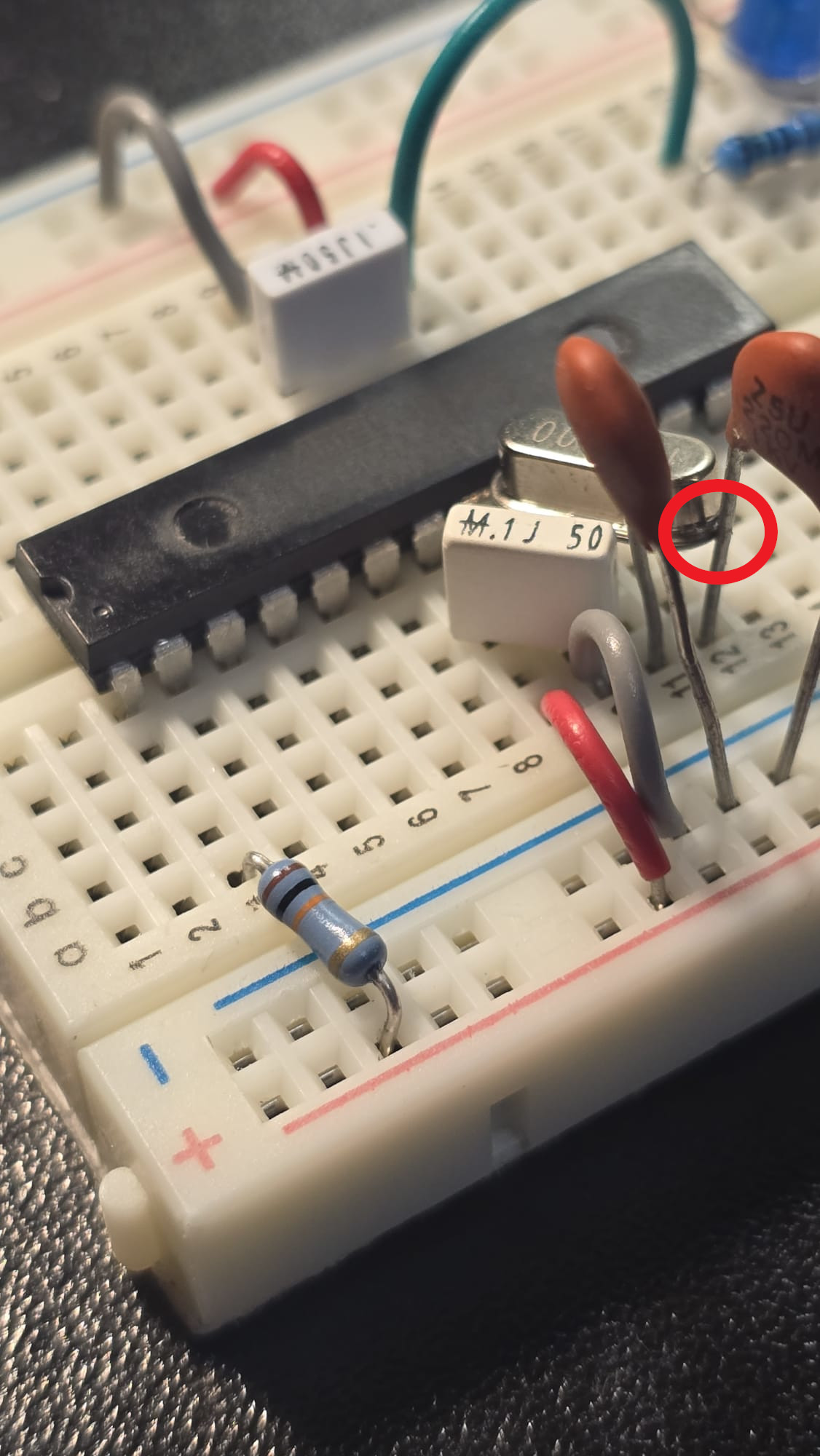
The 0.1uF cap from West to ground is recommended, but the circuit worked for me without that and without both the bypass caps. It even worked with the crystal body shorted to either 22pF cap lead.
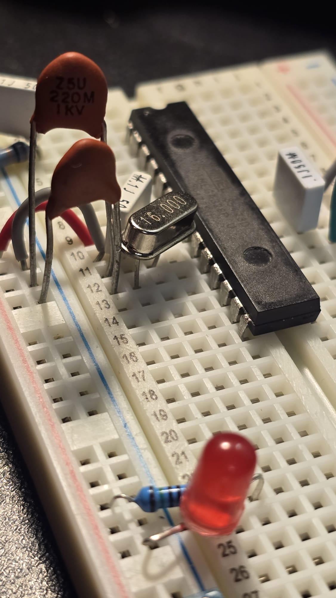
here is an updated picture of the breadboard with clear connection , nothing shorted, all as described and still not working . thats crazy, any help at this point is appreciated.