Hi guys,
I'm very beginner in Arduino.
I have one Arduino Mega and I bought one LCD 128x64 RG12864K-BIW-VBG RAYSTAR OPTRONICS
I tried to build my first project with Arduino and I used as reference to display: Graphic LCD 128x64 tutorial by Technowave G - YouTube
Also I use U8g2 to writte a simple Hello World 
My problem is, I have very, very low contrast on display, very hard I see that is something on display and also some lines is flickering
I'm asking, maybe someone have similar project and it's working and maybe can share with me wiring and library used.
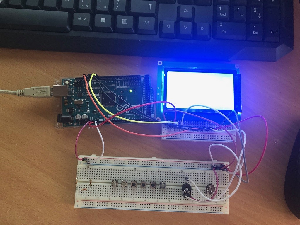
I attached some pictures, I don't know if is visible, but contrast it's maximum.
What i'm doing wrong, please some help
You don't need any contrast adjustment. The ST7920 module should run correctly by itself (if you supply 5V).
You just connect pins: 5V, GND, PSB, CS, MOSI, SCK. Do not connect anything to pin#17.
Your video "looks" like a parallel KS0108 module. The music was so annoying that I would not watch it.
David.
Thanks David for your answer.
In attach is pin out diagram of display(also i put in attach and pdf specs)
I cannot identify CS, MOSI, SCK pins from display specs.
Can you guide me ?
Thanks in advance for your time and patience with a beginner
RG12864K-BIW-VBG.pdf (648 KB)
Hi Studio72,
On the back of the display you will see a tiny unpretentious contrast regulating screw (I assume a potentiometer). Fetch a screwdriver and turn the screw!
good luck!
Hi @Photoncatcher,
There is no any potentiometer available.
see back.jpg picture from attach
Also I tried to put an potentiometer 10K to Vo, but I don't got any text on screen, only contrast it's working
I tried base on tutorial from this page
But display shows only 2 some of lines, see Proj_a and Proj_b picture
I succeed something using one example from U82G library.
But still display is not clear
I create a small video on Youtube
And this config
U8G2_ST7920_128X64_1_SW_SPI u8g2(U8G2_R0, /* clock=/ 13, / data=/ 11, / CS=/ 10, / reset=*/ 8);
Only with this is succeed to got something on LCD but still with flickering and some noise i think
Any ideea ?
I suggest that you install U8g2lib library and run the examples.
// ST7920 SPI: RS=CS, RW=MOSI, E=SCK, PSB=GND.
//U8G2_ST7920_128X64_1_SW_SPI u8g2(U8G2_R0, 13, 11, 10, /* reset=*/ U8X8_PIN_NONE); //
From your photo it looks like
GND - BLACK - VSS (1)
5V - RED - VDD (2)
digital #10 - BLACK - RS (4)
digital #11 - ORANGE - R/W (5)
digital #13 - YELLOW - E (6)
GND - RED - PSB (15)
5V - WHITE - BLA (19)
GND - WHITE - BLK (20)
Please remove any other wires. Run U8g2 examples with the above constructor.
I would expect everything to be 100% readable.
If the backlight is too bright, connect BLA to 5V via a 47R or 22R series resistor.
As a general rule. Use different colour wires consistently e.g. BLACK = GND, RED = 5V
Oliver's examples all work with tiny buffers like your U8G2_ST7920_128X64_1_SW_SPI() constructor.
But you can afford a full-fat buffer e.g. U8G2_ST7920_128X64_F_SW_SPI()
And you can use the MEGA2560 hardware SPI if speed is important.
In practice, 128x64 LCD do not like fast changes. So you might just stick to the SW_SPI() constructors.
My ST7920 has empty footprint for VR1. It gives fine contrast.
If you have contrast problem with my suggested wiring, please say so.
David.
Edit. I was typing while you posted. Your video has some slight glitches. I would check your jumper cables and breadboard for intermittent breaks.
Thanks @david_prentice
Same issue, some lines from LCD still flickering
This is the code for Hello World
#include <U8g2lib.h>

U8G2_ST7920_128X64_1_SW_SPI u8g2(U8G2_R0, 13, 11, 10, /* reset=*/ U8X8_PIN_NONE);

void setup() {

  u8g2.begin();

}

void loop() {
  // put your main code here, to run repeatedly:
    u8g2.firstPage();
  do {
    u8g2.setFont(u8g2_font_ncenB10_tr);
    u8g2.drawStr(0,24,"Hello World!");
  } while ( u8g2.nextPage() );
  //delay(1000);

}
Also I tried from U8g2 available examples
From menu Examples -> U8g2 -> Page_buffer -> GrapicsTest
with below wiring
LCD MEGA
1 GND
2 5V
3 POT for contrast
4 10
5 11
6 13
15 GND
19 5V
20 GND
and construnctor
U8G2_ST7920_128X64_1_SW_SPI u8g2(U8G2_R0, 13, 11, 10, /* reset=*/ U8X8_PIN_NONE);
Same result, on display flickering lines
I put a video on youtube with behavior
Any ideea ?
Remove the pot and any wires.
Now you have some spare conecting wires.
Run the program. Replace each signal wire in turn. i.e. YELLOW, ORANGE, BLACK.
Don't swap any power wires with the program running. But you can always "add" an extra power wire in parallel with the existing wires.
You should always do this sort of swap / parallel following a documented plan. i.e. write everything down on paper.
I would expect the Arduino soldering and the LCD module header pin soldering to be to a high stndard.
But jumper wires are always suspect. Likewise breadboard connections.
Think about it. If a video glitch appears at coordinate x,y consistently: a software problem.
If the glitches are random, it is a solder joint / wire / breadboard intermittent fault.
David.
I removed the Pot.
Nothing on screen now
Normally, I only connect to hardware displays via custom soldered Protoshields.
However, I connected to a Uno via a mini breadboard according to my suggested scheme.
Oliver's GraphicsTest_u8g2 is running just fine on my ST7920 LCD.
If removing the pot makes a difference to your display there is something unusual.
Please post a clear photo of your wiring.
David.
Incidentally, I used el-cheapo Chinese skinny male-male jumpers. Very unreliable jumpers. But worked first time.
I tried to arrange somehow wires to be easily identified.
Hope to be understandable
See attached photo (wiring.jpg)
You appear to have the LCD on a nice half breadboard (with + and - bus lines)
The LCD header pins look well soldered. The MEGA2560 looks good.
I would put all the wiring on this half breadboard.
5V, GND to + and - bus.
LEDK and PSB to - bus.
LEDA to + bus.
RS, RW, E to 10, 11, 13
As I said earlier. You do not need a pot. You do not need to connect to VO pin on LCD.
You appear to have LEDA connected to 3.3V pin. That is WRONG.
I would guess that most ST7920 boards are like mine. i.e. no need to connect VO or pot.
Perhaps other readers have different ST7920 displays.
Note that you have 5V and GND sockets on the 18x2 header socket. Shorter wires to breadboard.
David.
I just followed LCD data sheet, there is indicated a pot connected to V0
In attach is LCD data sheet "RG12864K-BIW-VBG.pdf"
I tried using your advice to direct connect LCD to Mega without POT
see attached picture "Without_POT_Direct_Wiring.jpg"
But on LCD only light working, no text, no image
see attached photo "Without_POT_Direct_LCD.jpg"
Added and POT I got some result with my LCD lines flickering
see attached photo "With_POT_Direct_Wiring.jpg" for wiring
and "With_POT_Direct_Wiring_LCD.jpg" for LCD result
Also I posted one movie to YouTube with my result connecting LCD directly to Mega
I really appreciate your support
Hi,
I fixed !
My beginner skills
It's was very hard to check the Arduino Mega pin out specs and Arduino Uno to see if there are some difference, way to read ?
Mega has CS=53, MOSI = 51, SCK = 52
Now it's working only with #include "U8glib.h" and constructor
U8GLIB_ST7920_128X64_4X u8g(52, 51, 53); // SPI Com: SCK = en = 18, MOSI = rw = 16, CS = di = 17
With U8G2 still lines flickering, maybe I don't know the constructor.
Any ideea ?
Another question,
I see on display that on middle and top of lcd are some lines with darkness contrast.
Which is the reason ?
Here a video with behavior Arduino Mega with LCD ST7920, strange lines - YouTube
Thanks a lot for support and advice's given
First off, I would plug the LCD into your half-breadboard.
I would put all the wiring on this half breadboard.
5V, GND to + and - bus.
LEDK and PSB to - bus.
LEDA to + bus.
RS, RW, E to 10, 11, 13
It appears that your LCD does require a connection on VO.
From your video, the pot "works" at 08:10 but the contrast disappears at 09:15. And any other setting further clockwise gives no picture.
If you have some resistors you could just connect a 470R between VO and GND. Forget about the pot.
Try different resistors e.g. 220R to 680R
There is nothing special about the pins in a SW_SPI constructor. You can use any pins e.g.
U8G2_ST7920_128X64_1_SW_SPI u8g2(U8G2_R0, 51, 52, 53, /* reset=*/ U8X8_PIN_NONE);
I have concluded that your glitches on 10, 11, 13 are either a broken jumper wire or a broken Arduino pin on 10, 11, 13.
So if the U8g2 program works on 51, 52, 53 I would just swap one signal at a time to establish which pin from 10,11,13 is damaged.
David.
Thanks David, you have totally right
I think I was little misunderstood,
LCD works with #include <U8glib.h> using 51, 52, 53 or 13,11,10
As you said, doesn't matter which pins I used in constructor
with U8g2 library, #include <U8g2lib.h>, using 51,52,53 or 13,11,10 same behavior with lines flickering on LCD.
Where is difference? Why U8g2 cant be used ?
Maybe I don't use the right constructor from U8g2lib
Any idea ?
Think about it. If a video glitch appears at coordinate x,y consistently: a software problem.
If the glitches are random, it is a solder joint / wire / breadboard intermittent fault.
You have made a video. You just compare subsequent runs with the video.
If glitches always appear at the same place, take notes.
Oliver will need to know about a software problem. It might be that your display is fussier with timing.
ST7920 is an established chip. My display works without glitches. I presume that everyone else's ST7920 display works with U8g2.
Wait for a few days. Oliver will see your message.
But make sure that you have given him accurate information. e.g. your wiring, constructor and time point(s) in video.
David.