Arduino Mega2560 and expander MCP23017

Hi,

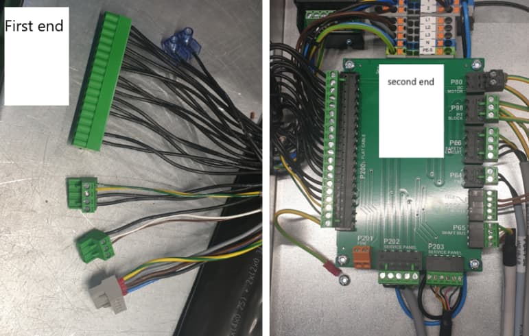
I'm trying to build a cable harness testare. The cable harness is composed of 27 cables. I'm using Arduino Mega2560 and MCP23017 to get enough IOs.
OUT_PIN[] array is to manage Arduino digital outputs
MCP_OUT_PIN[] array to manage the expander digital outputs
IN_PIN[] array is to manage Arduino digital inputs
MCP_IN_PIN[] array is to manage the expander digital inputs

I'm wondering if there is any way to iterate through the two output arrays and the same for the input arrays.

I tired to concatenate the two output/input arrays (OUT_PIN_TOTAL [] and IN_PIN_TOTAL[]) but I dont't think this will work. wheres as the output and input of expander IOs need to managed separately via Adafruit_MCP23X17 class.

#include <Wire.h>
#include <Adafruit_MCP23X17.h>
#include <LiquidCrystal_I2C.h>
#include <avr/wdt.h>

LiquidCrystal_I2C lcd(0x27, 20, 4);
Adafruit_MCP23X17 mcp;

uint8_t OUT_PIN[] = {30, 32, 34, 36, 38};
uint8_t IN_PIN[] = {40, 42, 44, 46, 48};

uint8_t MCP_OUT_PIN[] = {5, 6, 7};
uint8_t MCP_IN_PIN[] = {10, 9, 8};

uint8_t  OUT_PIN_TOTAL[8];
uint8_t  IN_PIN_TOTAL[8];

int NoContinuity;

#define MCP_INPUTPIN 2
#define MCP_LEDTOG1 11
#define MCP_LEDTOG2 3


int continuityResult[20];

int shortCableResult[20];
int wrongWiringResult[20];
int shortCableOnce[20];

int count = 0;
int startButton = 52;
int buttonState = 0;
int lastButtonState = 0;

int checkForFault = 0;
void setup() {
  mcp.begin_I2C();      // Default device address 0

 /* mcp.pinMode(MCP_LEDTOG1, OUTPUT);  // Toggle LED 1
  mcp.pinMode(MCP_LEDTOG2, OUTPUT);  // Toggle LED 2

  /*mcp.pinMode(MCP_LED1, OUTPUT);     // LED output
    mcp.digitalWrite(MCP_LED1, HIGH);

  //mcp.pinMode(MCP_INPUTPIN,INPUT);   // Button i/p to GND
  mcp.pinMode(MCP_INPUTPIN, INPUT_PULLUP);    // Puled high to ~100k
  // mcp.pullUp(MCP_INPUTPIN,HIGH); */

  Serial.begin(9600);
  lcd.init();
  lcd.clear();
  lcd.backlight();

  pinMode (startButton, INPUT_PULLUP);


  for (uint8_t i = 0; i < sizeof(OUT_PIN); i++)

  {
    pinMode(OUT_PIN, OUTPUT);
    digitalWrite(OUT_PIN, HIGH);

  }
    for (uint8_t i = 0; i < sizeof(IN_PIN); i++)

  {

    pinMode(IN_PIN, INPUT_PULLUP);


  }

  for (uint8_t i = 0; i < sizeof(MCP_OUT_PIN); i++)

  {
    pinMode(MCP_OUT_PIN, OUTPUT);
    digitalWrite(MCP_OUT_PIN, HIGH);

  }
 
  for (uint8_t i = 0; i < sizeof(MCP_IN_PIN); i++)

  {

    pinMode(MCP_IN_PIN, INPUT_PULLUP);


  }


  memcpy(OUT_PIN_TOTAL, OUT_PIN, sizeof(OUT_PIN));
  memcpy(OUT_PIN_TOTAL + sizeof(OUT_PIN), MCP_OUT_PIN, sizeof(MCP_OUT_PIN));


  memcpy(IN_PIN_TOTAL, IN_PIN, sizeof(IN_PIN));
  memcpy(IN_PIN_TOTAL + sizeof(IN_PIN), MCP_IN_PIN, sizeof(MCP_IN_PIN));

  lcd.setCursor(0, 0);
  lcd.print("PRESS START BUTTON");
  lcd.setCursor(0, 1);
  lcd.print("TO TEST NEW CABLE");

  Serial.println("Press START button to test new cable");


}

//**********************************************************************************

void loop()
{
  delay(300);

  /* mcp.digitalWrite(MCP_LEDTOG1, HIGH);
    //  mcp.digitalWrite(MCP_LEDTOG2, LOW);

    delay(300);

    mcp.digitalWrite(MCP_LEDTOG1, LOW);
    //mcp.digitalWrite(MCP_LEDTOG2, HIGH);

  // Transfer input pin state to LED1
  if (!mcp.digitalRead(MCP_INPUTPIN)) {
    mcp.digitalWrite(MCP_LEDTOG2, HIGH);
  } else {
    mcp.digitalWrite(MCP_LEDTOG2, LOW);
  }*/

  buttonState = digitalRead(startButton);  // read the pushbutton input pin


  if (buttonState != lastButtonState) // compare the buttonState to its previous state
  {

    if (buttonState == LOW) // if the state has changed, proceed the functions
    {

      checkForFault = shortCableTest();


      if (checkForFault >= 1)
      {

        fixTheError();
        goto repeatTest;
      }

      checkForFault = wrongWiringTest();
      if (checkForFault >= 1)
      {

        fixTheError();

        goto repeatTest;
      }

      checkForFault= continuityTest();
      if (checkForFault >= 1)
      {

        fixTheError();
        goto repeatTest;
      }

      else
      {
        lcd.clear();
        lcd.setCursor(0, 0);
        lcd.print("GOOD JOB,CABLE IS OK");
        lcd.setCursor(0, 2);
        lcd.print("PRESS START BUTTON");
        lcd.setCursor(0, 3);
        lcd.print("TO TEST NEW CABLE");
        Serial.println("GOOD JOB,CABLE IS OK");
        Serial.println("Press START button to test new cable");
      }

      delay(50); // Delay a little bit to avoid bouncing

    }

  }
repeatTest:
  lastButtonState = buttonState;

}

//**********************************************************************************

void fixTheError()
{
  lcd.setCursor(0, 2);
  lcd.print("FIX THE ERROR THEN");
  lcd.setCursor(0, 3);
  lcd.print("PRESS START BUTTON");
  Serial.println();
  Serial.println("Fix the error then press START button");
}
//**********************************************************************************

int shortCableTest()
{

  boolean shortCablePrint = true;
  int shortCableGroup = 0;


  for (uint8_t i = 0; i < sizeof(OUT_PIN_TOTAL); i++)
  {

    int shortCable = 0;

 for (uint8_t j = 0; j < sizeof(IN_PIN_TOTAL); j++)
  {
      if (!digitalRead(IN_PIN_TOTAL[j]) && shortCableOnce[j] == 0) //check if the combination of short cable has not alreday been taken
      {
        shortCableResult[j] = 1;
        shortCable++;

      }
    }
    if (shortCable < 2) //if no more than 2 outputs = 0 it means no shortcable
    {
      for (uint8_t j = 0; j < sizeof(IN_PIN_TOTAL); j++)
      {

        shortCableResult[j] = 0;

      }
    }
    else if (shortCable > 1)
    {
      shortCableGroup++;
      if (shortCableGroup > 1)
      {
        lcd.print(",");
      }
      for (uint8_t j = 0; j < sizeof(IN_PIN_TOTAL); j++)
      {

        if (shortCableResult[j] == 1)
        {
          shortCableOnce[j] = 1; //store all pins with short cable to an array
          if (shortCablePrint)
          {
            lcd.clear();
            lcd.setCursor(0, 0);
            lcd.print("SHORT CABLE ON PINS: ");
            lcd.setCursor(0, 1);
            Serial.print("SHORT CABLE ON PINS: ");
            shortCablePrint = false;
          }

          lcd.print(j + 1);
          Serial.print(j + 1);
          lcd.print(" ");
          Serial.print(" ");
          shortCableResult[j] = 0;
        }

      }
    }
nextI:
    digitalWrite(OUT_PIN_TOTAL[i], HIGH);

  
  for (uint8_t j = 0; j < sizeof(IN_PIN_TOTAL); j++)
  {
    shortCableOnce[j] = 0;
  }
  return shortCableGroup;
}

//**********************************************************************************

I've pasted only one rutin shortCableTest()

any help whould be very appriciated

Welcome to the forum.

Are there 27 wires and one of them is GND ? Do you want to detect a short circuit to GND as well ? Is there a shielding around the cable, or is that already included with those 27 wires ?

The Mega has 54 digital pins and the 16 analog pins can be digital pins as well. So the total is 70 pins. Minus 2 for the I2C bus and minus 2 for the Serial port at pin 0 and 1, then there are still 66 available pins.

I think the easiest way is a Arduino Uno with many MCP23017 or other I2C I/O expanders.
Can you use MCP23017 chips for all the I/O ?
If something bad happens and a voltage peak from the cable damages the Arduino board, then it is easier if all the MCP23017 chips are only connected with a few wires to the Arduino board, so you can easily swap the damaged part. Then you can also swap the Arduino board with any other Arduino board that you have lying around.

The Arduino functions for a pin can not be combined with the library for the MCP23017. It is possible to make a Class (perhaps with a Template) that encapsulates both.
Then you get this:

myOwnEncapsulatingClass.digitWrite(pin,state);

And inside the Class, the function does the routing to either the Arduino pin or the MCP23017 pin.

The overall structure of the code can be better. I don't understand why you need a memcpy() and using "goto" is almost never needed.

I agree with @Koepel about using several of the MCP23017 expanders and forgetting about using the Mega I/O pins. It will make life much simpler.

Approach 1(most robust):
Buy a Nano or Uno, or use the Mega because you already have it. Use 2 mcp23017 for input, 2 for output. Put each pair on daughter boards, so you can make boards with ANY connector with up to 32 pins, so you can test a different cable next year.
Approach 2(minimal up front cost): As noted by others, there are enough pins on the Arduino, just arrange them in two sets of 28(assuming you have a shield to test as well). Go to it. The first time something ugly happens, you'll be buying a new Mega, but hey, it will cost the least up front.

PC Board software is free, Schematic capture is part of it; PC boards are dirt cheap in small quantities. So if you want to make this a real project, there's that option, too. But you can do this all on a protoboard, it's just a lot of hand wiring.

Do you really mean 27 cables, of multiple wires (shield and gnd = 2 wires). Or do you mean 27 wires in the harness?

A Mega should be able to test 27 cables with the discrete pins.

some years ago I have written a short POC.
It tests each cable if it is connected to another cable:

Thank you every one for taking the time to answer my questions :slight_smile:
I'm sorry that I wasn't clear enough in my post. The cable harness is flatcabel which is composed of 27 cordes. It is not connected to any other devices. So waht I need to do is to test the both ends of the cable harness. that means I need preliminary 54 IOs. Some of cordes are connected to more than one terminal block (more IOs will be needed).
I dont's see any problem/risk to use Arduino IOS. Or what do you think guys?

As you see from images above. I need to iterate through digital inputs/outputs to detect if there's a short circuit, wrong wiring or no connection.
I'm not pretty sure how to make that possible when I'm using multiple expandes.
Is it possible to use the same "for loop" for multiple expanders?

Best regards
Yaser

Purpose of project is missing. Personal one-off? Business related? Commercial equipment testing?
All has a direct bearing on the answer.

Thank you @Koepel !
As I mentioned below. I need to iterate throug all digital inputs/outputs at the same time. How to make that possible?

Yes. I 'spit' data to up to MCP23017s configured variously as input and output without a problem, though I'll confess it took some thought, and experimentation, to make it work.

It's a private project. I'm trying to learn myself how to make everything possible by using an Arduino.
At work they have bought a universal cable tester which can do the job. But I was wondering if I can do by oneself
Hope it's clear for you now. :slight_smile:

Hi @jim-p ,
Why do you think using expanders simpler than using the Mega I/Os?

yaser79, we use the common "Reply" button at the bottom. That this easier on this forum.
You can select a text from someone with the mouse and then click "Quote". Like this:

Because then the circuit is more straightforward and as a bonus, the sketch is easier as well, and as a extra bonus, the board can also be a Arduino Uno or any other board.

@Koepel , thanx a lot to make it easier for me to use this forum.

I still need to manage how to use the same "for loop" for multiple expanders. I couldn't find some similar sketches on the forum.

Think this way:

  1. output all data to pins
    output data to one MCP
    output data to 2nd MCP port
    ...next MCP, repeat until done
  2. read all data from pins
    input data from one MCP
    input data from one MCP port
    input data from 2nd MCP port
    ...next MCP, repeat until done
  3. Compare data

Now, the data probably consists of a walking 0000001000000 pattern, or some such, so you'll do the above as many times as you have pins to set to 1, watching for the same pattern(or a different one) at the other end.
The trick is how you structure your data, code and your MCPs to make the above work easily. Think arrays and structs, if you've got those concepts down.
I'd throw my code at you, but at this point that would be counterproductive; 90% of it isn't about the MCP data, and sorting the wheat from the chaff would be a challenge for you.

This is my first attempt for a cable tester, I'm pretty sure that it is full of bugs, but fun to play with. Make the connections (open or short circuit) on the breadboard:

Wokwi has yet no MCP23017 I/O expander and it is low on the requested features list: Wokwi Roadmap - Vote for new features

[UPDATE]
I have rewritten this post, because I have accidentally made my Wokwi project "Cable Tester" over a previous example of a "Connection Scanner" and now the "Connection Scanner" is gone.

@camsysca , thanks a lot to enlighten me :slight_smile:
very instructively.
waiting for the code...

@Koepel, nice of you
But don't you need to add diodes to the output pins? in case of short circuit then the low output signal will be connected to a pulled up input pin.

in case of short circuit then the low output signal will be connected to a pulled up input pin

The only way you'll find a connection is with an output low and an input pulled up, so I'm not really sure what you think this is about. Please draw (pen-and-paper, photo, if necessary) the circuit you are concerned about.

Regarding output protection, at it's most basic you need "a circuit impedance" high enough to prevent damaging outputs wired to each other, either due to a cable short, or due to unusual cable configurations, if this is a possibility. This is one of the areas where commercial testers earn their keep; from what I've seen (a small sampling, 15 years ago) some drive each pin with a robust circuit, some employ PTC cutout technology, some apply a very short pulse to each pin, to avoid sustained currents; as a newbie designing a benchtop project, you'll make mistakes along the way that will leave outputs wired directly together for eons, so better to guard against that. If you want to learn, and you know the cables you'll be testing are generally 1-1, 2-2 etc. you can probably get away with just putting 200 ohms in series with each output to guard against the occasional out-to-out short and out-ground short, provided you also drive the ground with the same arrangement.

As for the code, I said I'm not providing it in it's entirety; it's big, cumbersome, turgid, and includes probably 200 lines of debug printouts that make it hard to read, but are essential to test and debug the different sections as it grows. If I feel the inspiration later today, I'll strip out the project to the 23017-specific bits and post it, but no guarantees. I'm retired, so it all depends on what HRH decides is the focus of the day...

No, the circuit is simple: Everything is pulled up with (internal) resistors and only one pin is made low. Then the pins are checked to see what else is pulled low.

With a very long cable, the noise might be too much for the weak internal pullup resistors.

@camsysca

Here's what I've ment.


Let us assume that output 1 low and other outputs high. and if you have short cable between input 1 and 2 then you will have low signal on output 2 while its status should be high.

But to connect a 200 ohm resistor in series with the output, it's something I should consider.