Cable harness tester with 3 connectors (<30 test points)

I’m working on a DIY cable harness tester project (to check continuity, cross-wiring, and resistivity) and could really use some guidance. As a newbie, I’ve hit a wall with both the schematic design and coding, and I’m not sure where to turn next.

What I’m trying to build:

  • A low-cost tester that can verify continuity between wire ends.
  • Detect cross-wiring/shorts between pins.
  • Measure resistance (for basic quality checks).
    I’m unsure how to design the circuit to handle multiple wires and avoid false readings and also struggling to write the code
  • You need to make an all inclusive list (preamble) on the functionality that’s need in this project.
    First off, the number of wires in the cable etc.
    *30 is the maximum ?
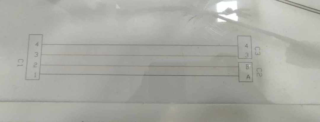
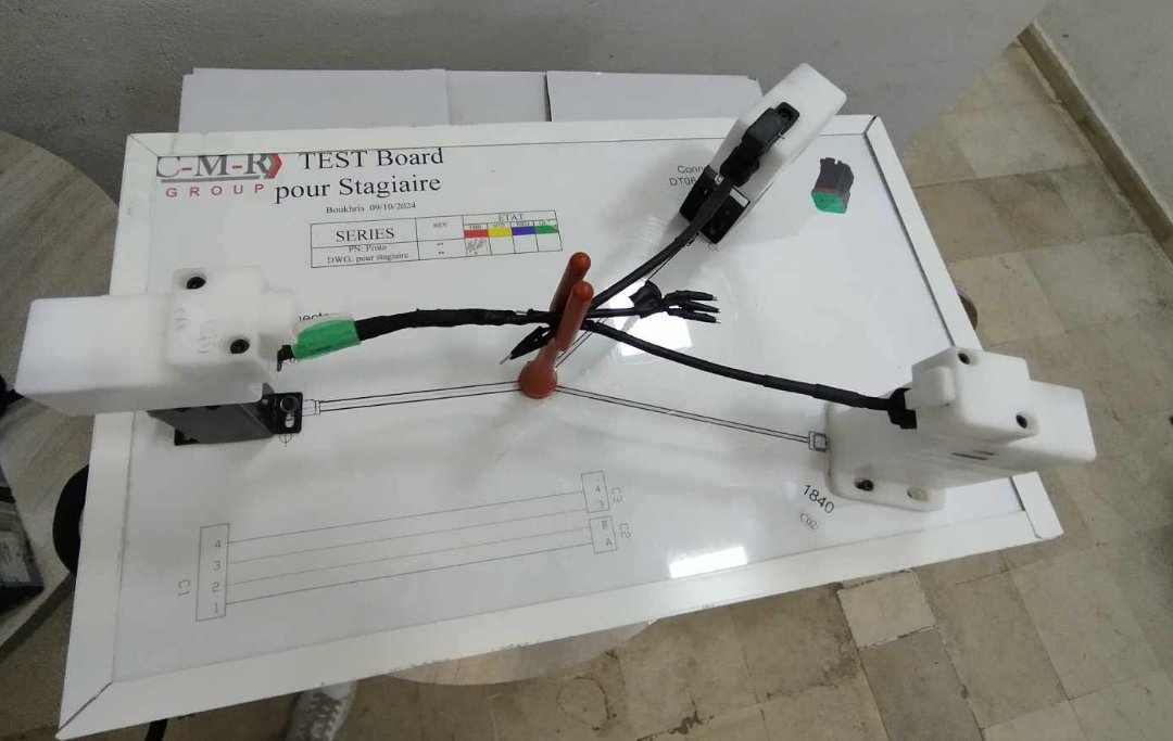
  • 3 Connectors as in a Y cable ?
  • Why are you making this ?
  • Show us an example of the most complicated cable that might be made.
  • Tell us what you have done in the past with electronics and Arduino.


  • Your I2C resistors should be pull-up connected, not in series.

  • Continuity only or resistive too ?

2 Likes

yes im working on small cables either they have 2 , 3 or 4 connectors
heres an example im working on


  • Why are you making this ?
    im doing an internship where they suggested for me to do a cable tester
1 Like

1st image its shows the mapping of the wire (drawing ) ,and 2nd image the wire im working on

I have one of the Cirrus wire harness tester it is a earlier version and can do 128 test connections.
I would suggest you just look at the products it might help you fill in the missing parts.

list of materlias that i have bought : power supply 5v/3a , AMS1117 , esp32 wroom , 2 muxs 16 channels ( im thinking to get a third one ) , lcd 16*2

  • Are these digital or analog multiplexors ?

  • Why did you select the ESP32 ?

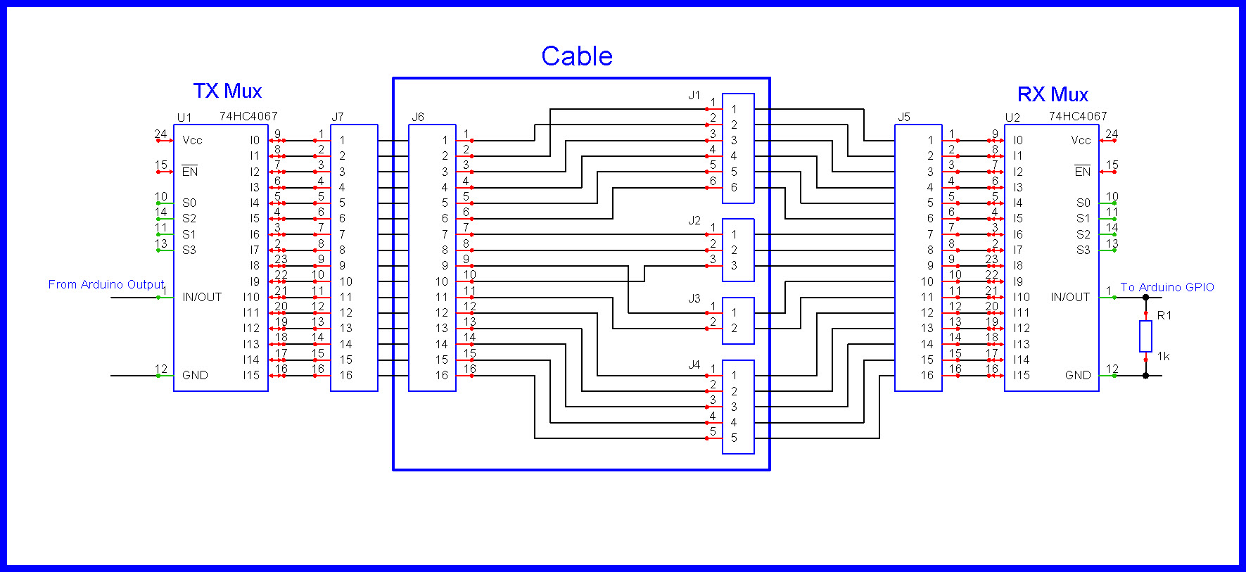
I have bought two mux's with this ref "cd74hc4067"

And I picked Esp32 cuz I'm gonna share the result not only through LCD but also on a dashboard (IoT) so I need a microship who has wi-fi integrated in it

  • Tell us what you have done in the past with hardware and software and Arduino ?

I’m still a beginner in embedded systems, but I’ve worked on a few Arduino projects, like a line-following robot and a temperature and humidity monitoring system. I mostly follow tutorials and experiment with small modifications, but I’m eager to improve my understanding of hardware and programming

  • 74HC4067 will work from Vcc = 2V thru 6 Volts, this is good for a 3V3 ESP32.

  • Your schematic showing a TX 4067 and a RX 4067 is reasonable; can obviously be expanded.

  • A one to one wire connection between I0-I15 of the multiplexors is made.

  • On a master cable:
    TX Mux: Place a HIGH/LOW on the MUX pin #1 (INPUT), select an output with S0-S3.
    RX Mux: Scan all the inputs on the RX Mux using S0-S3, monitor pin #1 (OUTPUT).
    Repeat until all wires are fingerprinted.

  • Above creates a finger print for that cable . . .

  • What exactly do you need help with ?

Your component list needs to include a keyboard so you can tell your program which exact cable you are testing!

  • Let's assume we have this schematic.
  • Let's assume the cable is supposed to be 1 to 1 wiring.
  • We walk a HIGH down the pins of the TX Mux, I0-I15
  • We make 16 reads to assemble a RX image as in the Cable101 array.
  • If this is a 1 to 1 cable, what is the problem with the cable ?

//Example of a 1 to 1, 16 wire cable
unsigned int Cable101[] =
  //Walk a 1 (one) down TX connector pins
  //TX wire# , zero based
  //111111
  //5432109876543210
{
  //RX Mux reading     //RX#
  0b0000000000000001,  //  0  assembled bits after 16 reads
  0b0000000000000010,  //  1
  0b0000000000000100,  //  2
  0b0000000000001000,  //  3
  0b0000000000010000,  //  4
  0b0000000000100000,  //  5
  0b0000000001000000,  //  6
  0b0000000010000000,  //  7  Finger print,
  0b0000000100000000,  //  8  sixteen 16 (32) bit reads
  0b0000001000000000,  //  9
  0b0000010000000000,  // 10
  0b0000100000000000,  // 11
  0b0001000000000000,  // 12
  0b0010000000000000,  // 13
  0b0100000000000000,  // 14
  0b1000000000000000   // 15
};

//===========================================================================
//Our faulty cable reads as this:
/*
  0b0000000000000010,  //  0  assembled bits after 16 reads
  0b0000000000000001,  //  1
  0b0000000000000100,  //  2
  0b0000000000001000,  //  3
  0b0000000000010000,  //  4
  0b0000000000100000,  //  5
  0b0000000001000000,  //  6
  0b0000000010000000,  //  7  Finger print,
  0b0000001000000000,  //  8  sixteen 16 (32) bit reads
  0b0000000100000000,  //  9
  0b0000010000000000,  // 10
  0b0000100000000000,  // 11
  0b0001000000000000,  // 12
  0b0010000000000000,  // 13
  0b0100000000000000,  // 14
  0b1000000000000000   // 15
*/
  • Can we simply tie IN/OUT on the TX Mux to Vcc ?
  • Let's say we had a 6 wire cable.
  • What would the RX array look like ?
  • Would you ever have a cable where ex. pin 7 is connected to pin 8 on the TX side ? :thinking:
    Or for that matter on the RX side ?

no, you wouldn't normally have a situation where pin 7 is connected to pin 8 on the same side (TX or RX)
or having a splice

its just follows the mapping that i showed you earlier

  • BTW, you would need a switch programmed for a short press and a long press.

  • A long press (say 3 seconds) reads a standard cable (learns its finger print), a short press (say < 1 second), compares the standard to the newly manufactured cable.


  • You have answers to give :thinking: .
  • Since your cabling is very simple, a resistor ladder would be appropriate.

  • There are R2R resistor networks available.

EDIT

Updated schematic.

so i should add R2R ladder resistor network on the RX side of multiplxer , and my schematic is good to go ?

#include <LiquidCrystal.h>

// Configuration des broches
const byte CONN_A[] = {22, 23, 24, 25}; // Connecteur A (4 pins)
const byte CONN_B[] = {26, 27};         // Connecteur B (2 pins)
const byte CONN_C[] = {28, 29};         // Connecteur C (2 pins)
const int BUTTON_PIN = 30;
const int R_REF = 1000; // Résistance de référence 1kΩ

// Mappage attendu (à adapter selon azert.jpg)
const byte EXPECTED_MAP[4][2] = {
  {26, 255}, // A0 -> B0 (pin 26), 255 = non connecté
  {27, 255}, // A1 -> B1 (pin 27)
  {28, 255}, // A2 -> C0 (pin 28)
  {29, 255}  // A3 -> C1 (pin 29)
};

struct WireResult {
  float resistance;
  byte connected_pins[2];
  byte error_type; // 0=OK, 1=Open, 2=Cross
};

WireResult results[4];

void setup() {
  Serial.begin(115200);
  pinMode(BUTTON_PIN, INPUT_PULLUP);
  initializePins();
}

void initializePins() {
  for(byte i = 0; i < 4; i++) pinMode(CONN_A[i], INPUT);
  for(byte i = 0; i < 2; i++) {
    pinMode(CONN_B[i], INPUT);
    pinMode(CONN_C[i], INPUT);
  }
}

WireResult testWire(byte src, byte expected1, byte expected2) {
  WireResult result = {INFINITY, {255, 255}, 1};
  
  pinMode(src, OUTPUT);
  digitalWrite(src, HIGH);
  delayMicroseconds(500);

  // Mesure sur toutes les broches
  for(byte b = 0; b < 2; b++) {
    if(checkConnection(src, CONN_B[b])) {
      result.connected_pins[0] = CONN_B[b];
      result.resistance = measureResistance(src, CONN_B[b]);
    }
  }
  for(byte c = 0; c < 2; c++) {
    if(checkConnection(src, CONN_C[c])) {
      result.connected_pins[1] = CONN_C[c];
      result.resistance = measureResistance(src, CONN_C[c]);
    }
  }

  // Analyse des résultats
  if(result.resistance != INFINITY) {
    bool valid = false;
    if(result.connected_pins[0] == expected1 || result.connected_pins[1] == expected2) valid = true;
    
    if(!valid) result.error_type = 2; // Cross-wiring
    else result.error_type = 0; // OK
    
    if(__builtin_popcount(result.connected_pins[0] + result.connected_pins[1]) > 1) {
      result.error_type = 2; // Multiple connections
    }
  }

  digitalWrite(src, LOW);
  pinMode(src, INPUT);
  return result;
}

float measureResistance(byte src, byte dest) {
  float v = analogRead(dest) * (5.0 / 1023.0);
  return (v > 0.1) ? ((5.0 - v) * R_REF / v) : INFINITY;
}

bool checkConnection(byte src, byte dest) {
  return (analogRead(dest) > 50); // Seuil de détection
}

void performTest() {
  Serial.println("\n=== TEST START ===");
  
  for(byte i = 0; i < 4; i++) {
    results[i] = testWire(CONN_A[i], EXPECTED_MAP[i][0], EXPECTED_MAP[i][1]);
    
    Serial.print("A");
    Serial.print(i);
    Serial.print(": ");
    
    switch(results[i].error_type) {
      case 0:
        Serial.print("OK -> ");
        if(results[i].connected_pins[0] != 255) {
          Serial.print("B");
          Serial.print(results[i].connected_pins[0] - 26);
        }
        if(results[i].connected_pins[1] != 255) {
          Serial.print("C");
          Serial.print(results[i].connected_pins[1] - 28);
        }
        Serial.print(" (");
        Serial.print(results[i].resistance, 1);
        Serial.println("Ω)");
        break;
        
      case 1:
        Serial.println("OPEN CIRCUIT");
        break;
        
      case 2:
        Serial.print("CROSS-WIRED -> ");
        for(byte j = 0; j < 2; j++) {
          if(results[i].connected_pins[j] != 255) {
            Serial.print(results[i].connected_pins[j] >= 28 ? "C" : "B");
            Serial.print(results[i].connected_pins[j] - (results[i].connected_pins[j] >= 28 ? 28 : 26));
            Serial.print(" ");
          }
        }
        Serial.println();
        break;
    }
  }
  Serial.println("=== TEST END ===\n");
}

void loop() {
  if(!digitalRead(BUTTON_PIN)) {
    delay(50);
    performTest();
    while(!digitalRead(BUTTON_PIN));
  }
}

Can you check if there are any mistakes or issues in this code?