Arduino Micro disconnects while program is running

Hi!

I am using an arduino micro to control a mosfet using pwm. The mosfets drain is connected to a load which is connected to a laboratory power supply. However, as soon as current starts to flow, the program interrupts and the COM port is disconnected too.

The thing is: this does not happen every time. Sometimes I can get like 400mA to the load. Sometimes it doesnt let current flow at all.

And another thing is: If I use this ciruit and use an Arduino Uno instead, it dont have that problem at all.

I have already read in other forums that this might be because Micro has some kind of fuse that resets the micro once too much current flows, or something like that.. but is that reasonable? The laboratory power supply is only connected to the load actually, so the current from the lab. power supply does not even "get in touch" with Micro? At least I think so.

Additionally I have encountered problems with micro before (randomly sitching COMports that are not even available etc.)

Can somebody please help me out?

sounds like a power supply problem
can you upoload a schematic of the circuit?
also the code (using code tags </>)

Well I have started by moving your post from the section that is only about getting the IDE to work and specifically asks you not to post your problems in it.

Please be more careful where you post in future.

As to your problem, your explanation is a bit short on actual details.

I that is so then it might be your problem. Your bench supply must have its ground connected to the ground of your Arduino to work correctly.

Please post a block diagram of your system showing how each component is connected together.

Also your load, you don't say what it is.
Is it inductive, like a motor or solenoid?
If it is what precautions have you taken to avoid the interference it will generate?

here is the code

#include <math.h>

const int Led_Green = 9;  
const int Led_Yellow = 10;  
const int Gate1 = 5;
const int Gate2 = 6;
const int Joystick_X = A0; 
const int Joystick_Y = A1;
const int pushbutton = 3;
int JoystickValue_X = 0; 
int JoystickValue_Y = 0;
const int middle_X = 512;
const int middle_Y = 512;
int pushbuttonState;
int JoystickValue_X_Y;

int tempsensor1 = A2;
int tempsensor2 = A3;
int tempsensor3 = A4;

int readVal1 = 0;
int readVal2 = 0;
int readVal3 = 0;

double Temp1 = 0;
double Temp2 = 0;
double Temp3 = 0;
int TempLimit;

double offset_degree;

double offset_degree1 = -2.2; // RT=26.0°C, difference
double offset_degree2 = 0.7;
double offset_degree3 = -2.47;

unsigned long deltaTime;

bool running = true;

//Define experiment (0 = manual, 1 = vollgas, 2 = , 3 = )
int experiment = 0; 

//Define functions--------------------------------------------------------------------
void manual_function() {
      
      JoystickValue_X = analogRead (Joystick_X);                        // [0, 1023]
      JoystickValue_X = constrain(JoystickValue_X, middle_X, 1023);     // [512, 1023]
      JoystickValue_X = map(JoystickValue_X, middle_X, 1023, 0, 1023);   // [0, 100]

 
      JoystickValue_Y = analogRead (Joystick_Y);                        // [0, 1023]
      JoystickValue_Y = constrain(JoystickValue_Y, middle_Y, 1023);     // [512, 1023]
      JoystickValue_Y = map(JoystickValue_Y, middle_Y, 1023, 0, 1023);   // [0, 100]

        Serial.print(Temp1);   
        Serial.print(";");      
        Serial.print(Temp2);  
        Serial.print(";");   
        Serial.print(Temp3); 
        Serial.print(";");
  
        Serial.print(JoystickValue_X);
        Serial.print(";");
        Serial.println(JoystickValue_Y);          
}


//Funktion Temperatur offset und Umrechung-----------------------------------------------------
double Thermistor(int RawADC, int sensor_number)
{
    double Temp;
    double offset_degree;
    Temp = log(10000.0 * ((1024.0 / RawADC - 1)));
    Temp = 1 / (0.001129148 + (0.000234125 + (0.0000000876741 * Temp * Temp )) * Temp );
    Temp = Temp - 273.15;            // Konvertierung von Kelvin in Celsius

    switch (sensor_number) {
  case 1:
    offset_degree = offset_degree1;
    break;
  case 2:
    offset_degree = offset_degree2;
    break;
   case 3:
    offset_degree = offset_degree3;
    break;
  default:
    offset_degree = 0;   
    break; 
}
    return Temp+offset_degree;
}

 
//-----------------------------------------------------------------------------------------------

void case_function( int JoystickInput_X, int JoystickInput_Y, int TempLimit, int TempValue) {    
    if(deltaTime < 45000L) {
    JoystickValue_X = JoystickInput_X;
    JoystickValue_Y = JoystickInput_Y;
        Serial.print(Temp1);   
        Serial.print(";");      
        Serial.print(Temp2);  
        Serial.print(";");   
        Serial.print(Temp3); 
        Serial.print(";");
  
        Serial.print(JoystickValue_X);
        Serial.print(";");
        Serial.println(JoystickValue_Y);  
    }
    else if ((deltaTime >= 45000L) && (TempValue > TempLimit)) {
     JoystickValue_X = 0;
     JoystickValue_Y = 0;
        Serial.print(Temp1);   
        Serial.print(";");      
        Serial.print(Temp2);  
        Serial.print(";");   
        Serial.print(Temp3); 
        Serial.print(";");
  
        Serial.print(JoystickValue_X);
        Serial.print(";");
        Serial.println(JoystickValue_Y);  
    }
    else if ((deltaTime > 45000L) && (TempValue < TempLimit)) {
      Serial.print("Experiment done.");
      running = false;
      
    }
    
}
//---------------------------------------------------------------------------------

void setup() {
  pinMode(Joystick_X, INPUT); // X-axis
  pinMode(Joystick_Y, INPUT); // Y-axis
  pinMode(pushbutton,INPUT); // press button
  digitalWrite(pushbutton, INPUT_PULLUP);
  pushbuttonState = digitalRead(pushbutton);
      
  Serial.begin(9600); 
  while (digitalRead(pushbutton) == HIGH);

}

void loop() {
  if(running == true) {
    //currentTime = millis();
    //unsigned long deltaTime = CalculateDeltaTime();
    static unsigned long TimeZero = millis();
    deltaTime = millis() - TimeZero;
    
      Serial.print("start");
      Serial.print(";");
      Serial.print(deltaTime);
      Serial.print(";");
      
      readVal1 = analogRead(tempsensor1);
      Temp1 =  Thermistor(readVal1,1);

      readVal2 = analogRead(tempsensor2);
      Temp2 =  Thermistor(readVal2,2);

      readVal3 = analogRead(tempsensor3);
      Temp3 =  Thermistor(readVal3,3);

     switch(experiment) {
      case 0:
        manual_function();
        break;
    
    
       case 1:
         case_function(1023, 0, 18, Temp1);

         break;
    
       case 2:
         case_function(0, 1023, 23, Temp2);
         break;
    
       case 3:
         case_function(1023, 1023, 23, Temp3);
         break;
    
       case 4:
         case_function(1023, 0, 36, Temp1);
         break;
    
       case 5:
         case_function(0, 1023, 36, Temp2);
         break;
    
       case 6:
         case_function(1023, 1023, 36, Temp3);
         break;
     
 }
         if (JoystickValue_Y <= 0) {
      analogWrite(Led_Green, 0);
      analogWrite(Gate1, 0);
    }
  
    if (JoystickValue_Y > 0) {
      analogWrite(Led_Green, JoystickValue_Y/4);
      analogWrite(Gate1, JoystickValue_Y/4);
    }
    
  
   if (JoystickValue_X <= 0) {
      analogWrite(Led_Yellow, 0);
      analogWrite(Gate2, 0);
    }
  
   if (JoystickValue_X > 0) {
      analogWrite(Led_Yellow, JoystickValue_X/4);
      analogWrite(Gate2, JoystickValue_X/4);
    }
       delay(1000);
      }
}
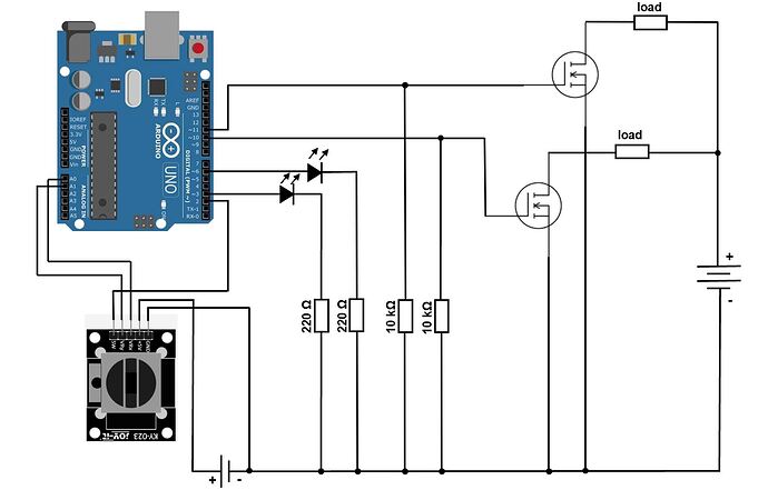
yes the all components have common ground. The load is just a resistance wire with R = 4-5 Ohm. The lab. power supply has a voltage of 3.6V.

I can't see anything that could cause the problem you are getting, although your diagram is odd showing batteries instead of power supplies.

The code has a couple of problems, but not any that would cause any problems.

  1. Analogue connections should be referred to by their number like 0 not A0. A is for use when an analogue input is being used as a digital pin. But it is such a common mistake that they have fixed it so the compiler makes the change for you.
  2. Pins used as analogue inputs do not need declaring as inputs in the setup function with the pinMode call.
  3. On an Arduino with an ATMega chip, like nano, uno or micro, there is no difference between float and double variables, they are the same resolution.

So nothing to cause you a problem.
You do have code that accesses pins that have nothing connected to them, this means the pins are floating which in general is not a good idea.

All that leaves is the actual hardware, What exactly are the part numbers of those FETs?
Are you using solderless bread board?
That can make it difficult to make connections to things like FETs, depending on the package type. And all solderless bread boards are prone to not making reliable connections.

That is rubbish.

If you draw too much current from the 5V output while powering it from the Vin or barrel jack, then the regulator chip on the uno can get too hot which can cause it to shut down, if your lucky. But it also can cause it to be damaged and not work again.

I don't see any ground connection on the Arduino.

1 Like

Well spotted, although, I think the "battery" close to the joystick is supposed to be the supply from the Arduino.

I am using this mosfet: https://cdn-reichelt.de/documents/datenblatt/A100/EN.CD00003408-1222794.pdf

and the circuit is soldered to a perfboard.

Thanks for the corrections on the code

oh youre right, its just missing in the figure tho

Hi,
How are you powering the Arduino?

Please update your circuit diagram and place in a new post.

Can you please post some images of your project so we can see your component layout?

Thanks.. Tom.. :smiley: :+1: :coffee: :australia:

Totally disagree with this. It is completely proper to refer to the pins with the Ax designation, and prevents confusion between needing the Ax when using pinMode, digitalRead, digitalWrite, etc, but being allowed to use either the number or Ax designation for analogRead.

The Ax designation is replace by an actual pin number by the compiler, as defined in the pins_arduino.h file, and in the case of a micro would properly be 18, not 0, when using A0. Note that this number is different depending on the processor being used, code portability is why the Ax notation exists.

The Micro has a native USB port (the USB hardware is integral to the processor itself). When the processor resets, the USB connection will disconnect, then reconnect after being re-initialized by the code. The UNO has an external chip used as a serial to USB bridge, when the atmega328 processor on the UNO resets, it has no affect on this external chip, so the USB connection is maintained.

I found the mistake and its a really stupid one! I soldered the the source pin to the wrong place on the ground...

But now its working again

Right now your other big big problem is that you are not using a logic level FET. That FET if you look at the Rds value only fully turns on with 10V on the gate. By using 5V it is hardly turning it on at all.
The threshold value is for where it turns off. So you are running in a sort of no man's land, and that will give you a problem with overheating.

But for how long? It really is an accident waiting to happen.

You haven't been around here very long have you. The fact that the compiler corrects your mistake is no excuse for not doing it right in the first place.

Obviously I have not been around long enough, most of the discussions I've seen are about the confusion caused by analogRead() NOT requiring the Ax designation.

This topic was automatically closed 180 days after the last reply. New replies are no longer allowed.