Hi,
I try to get the Card Info sketch running which I did not modify besides the line where the chipSelect PIN is choosen.
I put it to: const int chipSelect = 10;
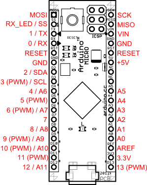
See the wiring as in attached diagram. The text color of the SD card terminals is red and the text stands close to the Arduino Micro terminals.
When I run the sketch I come into the !card.init section which tells me that something went wrong.
Does anybody has an idea what's wrong here ? Was the wiring correct ? Did I choose the right chipSelect PIN ?
Thank you
Regards
AgeBee
/*
  SD card test

 This example shows how use the utility libraries on which the'
 SD library is based in order to get info about your SD card.
 Very useful for testing a card when you're not sure whether its working or not.

 The circuit:
  * SD card attached to SPI bus as follows:
 ** MOSI - pin 11 on Arduino Uno/Duemilanove/Diecimila
 ** MISO - pin 12 on Arduino Uno/Duemilanove/Diecimila
 ** CLK - pin 13 on Arduino Uno/Duemilanove/Diecimila
 ** CS - depends on your SD card shield or module.
 		Pin 4 used here for consistency with other Arduino examples


 created  28 Mar 2011
 by Limor Fried
 modified 9 Apr 2012
 by Tom Igoe
 */
 // include the SD library:
#include <SD.h>

// set up variables using the SD utility library functions:
Sd2Card card;
SdVolume volume;
SdFile root;

// change this to match your SD shield or module;
// Arduino Ethernet shield: pin 4
// Adafruit SD shields and modules: pin 10
// Sparkfun SD shield: pin 8
const int chipSelect = 10;

void setup()
{
 // Open serial communications and wait for port to open:
  Serial.begin(9600);
   while (!Serial) {
    ; // wait for serial port to connect. Needed for Leonardo only
  }


  Serial.print("\nInitializing SD card...");
  // On the Ethernet Shield, CS is pin 4. It's set as an output by default.
  // Note that even if it's not used as the CS pin, the hardware SS pin
  // (10 on most Arduino boards, 53 on the Mega) must be left as an output
  // or the SD library functions will not work.
  pinMode(10, OUTPUT);     // change this to 53 on a mega


  // we'll use the initialization code from the utility libraries
  // since we're just testing if the card is working!
  if (!card.init(SPI_HALF_SPEED, chipSelect)) {
    Serial.println("initialization failed. Things to check:");
    Serial.println("* is a card is inserted?");
    Serial.println("* Is your wiring correct?");
    Serial.println("* did you change the chipSelect pin to match your shield or module?");
    return;
  } else {
   Serial.println("Wiring is correct and a card is present.");
  }

  // print the type of card
  Serial.print("\nCard type: ");
  switch(card.type()) {
    case SD_CARD_TYPE_SD1:
      Serial.println("SD1");
      break;
    case SD_CARD_TYPE_SD2:
      Serial.println("SD2");
      break;
    case SD_CARD_TYPE_SDHC:
      Serial.println("SDHC");
      break;
    default:
      Serial.println("Unknown");
  }

  // Now we will try to open the 'volume'/'partition' - it should be FAT16 or FAT32
  if (!volume.init(card)) {
    Serial.println("Could not find FAT16/FAT32 partition.\nMake sure you've formatted the card");
    return;
  }


  // print the type and size of the first FAT-type volume
  uint32_t volumesize;
  Serial.print("\nVolume type is FAT");
  Serial.println(volume.fatType(), DEC);
  Serial.println();

  volumesize = volume.blocksPerCluster();    // clusters are collections of blocks
  volumesize *= volume.clusterCount();       // we'll have a lot of clusters
  volumesize *= 512;                            // SD card blocks are always 512 bytes
  Serial.print("Volume size (bytes): ");
  Serial.println(volumesize);
  Serial.print("Volume size (Kbytes): ");
  volumesize /= 1024;
  Serial.println(volumesize);
  Serial.print("Volume size (Mbytes): ");
  volumesize /= 1024;
  Serial.println(volumesize);


  Serial.println("\nFiles found on the card (name, date and size in bytes): ");
  root.openRoot(volume);

  // list all files in the card with date and size
  root.ls(LS_R | LS_DATE | LS_SIZE);
}

void loop(void) {

}

