Have a good day. I am new to Arduino coding. I tried many programs on the internet to get the kg information from the weight indicator I have and write it to the serial port, but I failed. I need help from those who have experience with Arduino modbus master. I have a ttl to rs485 converter MAX485. I was able to read the kg information from the computer with Modbus Poll. I would be glad if you help me with a program that will write the kg information to the Arduino serial port screen.
The Modbus Master Library from DocWalker is a good start.
Show us your wiring - we need to see to which Arduino pins you have connected to DI, RO, DE/RE
It would also help if you posted the code you were using. Remember to place it between code tags otherwise it'll be hard to read and likely incur the wrath of the moderators
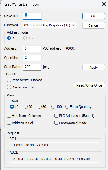
I have uno, nano and pro mini. I tried many programs related to Arduino uno. I usually connected DI, RO, DE/RE according to the pins in the codes I found. DE/RE is usually combined into a single pin. I did not share the codes because I could not run them. If I find a code that I think will work with corrections, I will share it. If you have a Modbus master program that reads records from only one address, could you share it? In the Modbus tool, I read kg as low and high from address dec 0 plc 40001.
/*******************************************************
Modbus Client Example D 485halfduplex
This Modbus Client
- reads registers from Modbus Servers periodically
based on an idea or the (incorrect):
RS485_HalfDuplex.pde - example using ModbusMaster library to communicate
reading M02 using a half-duplex RS485 transceiver.
hardware
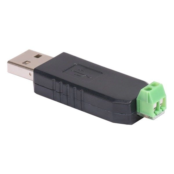
- a MAX485-TTL adapter
by noiasca
2024-10-27 https://forum.arduino.cc/t/arduino-modbus-master-help-please/1315703
2022-07-31 OK - tested with Arduino MEGA
*******************************************************/
/* *******************************************************
Serial Interface
* **************************************************** */
// if you don't have enough HW Serial (i.e. on an UNO)
// you are forced to use SoftwareSerial or AltSoftSerial
include <SoftwareSerial.h>
constexpr uint8_t rxPin = 2; // for Softserial
constexpr uint8_t txPin = 3;
SoftwareSerial mySerial(rxPin, txPin);
// On a Mega you can simply use
// a Reference to an existing HW Serial:
//HardwareSerial &mySerial = Serial3;
/* **************************************************** *
Modbus
* **************************************************** */
#include <ModbusMaster.h> // Modbus Master 2.0.0 by Doc Walker - install with Library Manager
constexpr uint8_t modbusEnablePin = 5; // The GPIO used to control the MAX485 TX pin. Set to 255 if you are not using RS485 or a selfsensing adapter
constexpr uint32_t modbusBaud = 9600; // use slow speeds with SoftSerial
constexpr uint16_t modbusRestTx = 15000; // rest time between transmissions - microseconds
uint32_t modbusPreviousTx = 0; // timestamp of last transmission - microseconds
ModbusMaster serverA; // instantiate ModbusMaster object - slave - node
// this function will be called before the client transmits data
void preTransmission()
{
while (micros() - modbusPreviousTx < modbusRestTx) // check last transmission end and wait if the call was to early
{
yield(); // wait some time and allow background tasks
}
digitalWrite(modbusEnablePin, HIGH);
}
// this function will be called after the transmission
void postTransmission()
{
digitalWrite(modbusEnablePin, LOW);
modbusPreviousTx = micros(); // remember last timestamp
}
// do all the settings for the Modbus
void modbusInit()
{
mySerial.begin(modbusBaud); // initialize Modbus communication baud rate
serverA.begin(1, mySerial); // communicate with Modbus server ID over the given Serial interface
pinMode(modbusEnablePin, OUTPUT); // Init enable pins for modbus master library
digitalWrite(modbusEnablePin, LOW);
serverA.preTransmission(preTransmission); // Callbacks allow us to configure the RS485 transceiver correctly
serverA.postTransmission(postTransmission);
}
// getdata from Modubs Server(Slave) and print to Serial
void requestData()
{
constexpr uint16_t interval = 5000; // interval of modbus requests
static uint32_t previousMillis = -interval; // timestamp of last request
uint32_t currentMillis = millis();
if (currentMillis - previousMillis > interval) // set the interval in ms
{
previousMillis = currentMillis;
uint16_t reg = 0x0;
int result;
result = serverA.readInputRegisters(reg, 2); // request from startregster, n Registers
if (result == serverA.ku8MBSuccess) // do something if read is successfull
{
Serial.print(F("LOW : ")); Serial.println(serverA.getResponseBuffer(0x00));
Serial.print(F("High: ")); Serial.println(serverA.getResponseBuffer(0x01));
}
else
{
Serial.print(F(" ServerA no success register ")); Serial.print(reg, HEX); Serial.print(F(" result=")); Serial.println(result, HEX);
}
}
}
/* **************************************************** *
setup and loop
* **************************************************** */
void setup()
{
Serial.begin(115200);
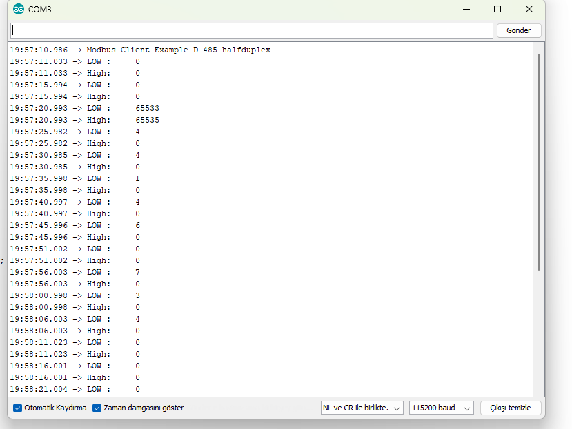
Serial.println(F("Modbus Client Example D 485 halfduplex"));
modbusInit();
}
void loop()
{
requestData();
}
but it would have been far easier for you if you had provided the information I asked for.
I found this code from the site below but I couldn't edit it according to my weight indicator. Can you help me with this? I just want to read the kg data at address 40001 according to dec 0, hex 0, plc address. 3 different data are read in this code. I added the weight indicator user manual.
// github link: https://github.com/4-20ma/ModbusMaster
#include <ModbusMaster.h>

/* Modbus stuff */
#define MODBUS_DIR_PIN  5 // connect DR, RE pin of MAX485
#define MODBUS_RX_PIN 0 // Rx pin
#define MODBUS_TX_PIN 1 // Tx pin
#define MODBUS_SERIAL_BAUD 9600 // Baud rate for modbus rtu communication

// voltage, current and frequency register of Energy Meter
// if you want to read more parameters, then increase the array size
//and, write the address
uint16_t data_register[3] = {0x0000, 0x0008, 0x0036};

//Initialize the ModbusMaster object as node
ModbusMaster node;

// Pin 4 made high for Modbus transmision mode
void modbusPreTransmission()
{
  delay(500);
  digitalWrite(MODBUS_DIR_PIN, HIGH);
}

// Pin 4 made low for Modbus receive mode
void modbusPostTransmission()
{
  digitalWrite(MODBUS_DIR_PIN, LOW);
  delay(500);
}

void setup() {
  //we initialize the built-in hardware serial communication
  //using the Serial.begin() function with two parameters.
  //The first parameter is the desired baud rate (9600 bits per second),
  //and the second parameter is SERIAL_8E1,
  //which specifies the data format (8 data bits, even parity, and 1 stop bit).
  //to set these two parameter, please read your sensor datasheet first
  Serial.begin(9600, SERIAL_8E1);
  while (!Serial) {
    ; // wait for serial port to connect. Needed for native USB port only
  }

  pinMode(MODBUS_DIR_PIN, OUTPUT);
  digitalWrite(MODBUS_DIR_PIN, LOW);

  //modbus device slave ID 14
  node.begin(14, Serial);

//  callbacks allow us to configure the RS485 transceiver correctly
   node.preTransmission(modbusPreTransmission);
   node.postTransmission(modbusPostTransmission);
}

void loop()
{
    uint8_t result;
    //for store 32-bit data
    uint16_t data[2];
    int i;
    float reading;
    // this loop is to read voltage, current and power factor register of Energy Meter
    for(i=0; i<=2; i++){
      //Modbus function code (0x04) Read Input Registers according to energy meter datasheet
      result = node.readInputRegisters(data_register[i], 1);

        if (result == node.ku8MBSuccess) {
          Serial.println("Success, Received data: ");

          //Retrieve the data from getResponseBuffer(uint8_t u8Index) function.
          //that is return 16-bit data. our energy meter return 32-bit data everytime.
          //that's why, we take the value to a array called data
           data[0]=node.getResponseBuffer(0x00);
           data[1]=node.getResponseBuffer(0x01);

           //read voltage
           if(data_register[i] == 0x0000){
            Serial.print("Volatge: ");
            reading = *((float *)data);
            Serial.print(reading);
            Serial.println(" Volt");
           }
           //read current
           if(data_register[i] == 0x0008){
            Serial.print("Current: ");
            reading = *((float *)data);
            Serial.print(reading);
            Serial.println(" Amps");
           }
           //read Frequency
           if(data_register[i] == 0x0036){
            Serial.print("Frequency: ");
            reading = *((float *)data);
            Serial.print(reading);
            Serial.println(" Hz");
           }
        } else {
          Serial.print("Failed, Response Code: ");
          Serial.print(result, HEX);
          Serial.println("");
          delay(5000);
        }

    }
  //one second delay
    delay(1000);
  }
Mixing the modbus and the printout on one Serial is not the best idea.
You could use SoftSerial with Pin 2 and 3 as in my sketch. and use HW-Serial (0, 1) for the debug infomation to Serial Monitor.
doesn't tell much.
If you don't see ANY output on the Serial Monitor - your wiring might be faulty.
You MUST be able see the Serial.println from setup().
/**
ModbusMaster response timed out exception.

The entire response was not received within the timeout period,
ModbusMaster::ku8MBResponseTimeout.

@ingroup constant
*/
The master doesn't receive an answer.
I suspect a wrong wiring not fitting to the code.
Do you understand now why I ask for pictures?!?
I made the connections like this. I couldn't find where I made a mistake. I didn't know if the weight indicator modbus settings were suitable for this code or not. I changed the settings and tried again and again. Thank you for your help.
Could you drop the baud rate back to 9600 and try the code on post #6 . Rx on 2 and Tx on 3 like that code defines.
Abandon your will to use pins 0 and 1 for now.
Result 1 means illegal function exception. That means you have response from your device.
Replace this line: result = serverA.readInputRegisters(reg, 2);
with
result = serverA.readHoldingRegisters(reg, 2);
Yes it worked. Thanks for your help. How can we increase the scanning speed? Data does not come instantly. Rows come very late. When I press the loadcell in reverse - signed numbers appear as numbers with 65555 on the serial port. - How can I print signed numbers as 0?