Arduino nano + 16x2 lcd for soldering station, weird characters

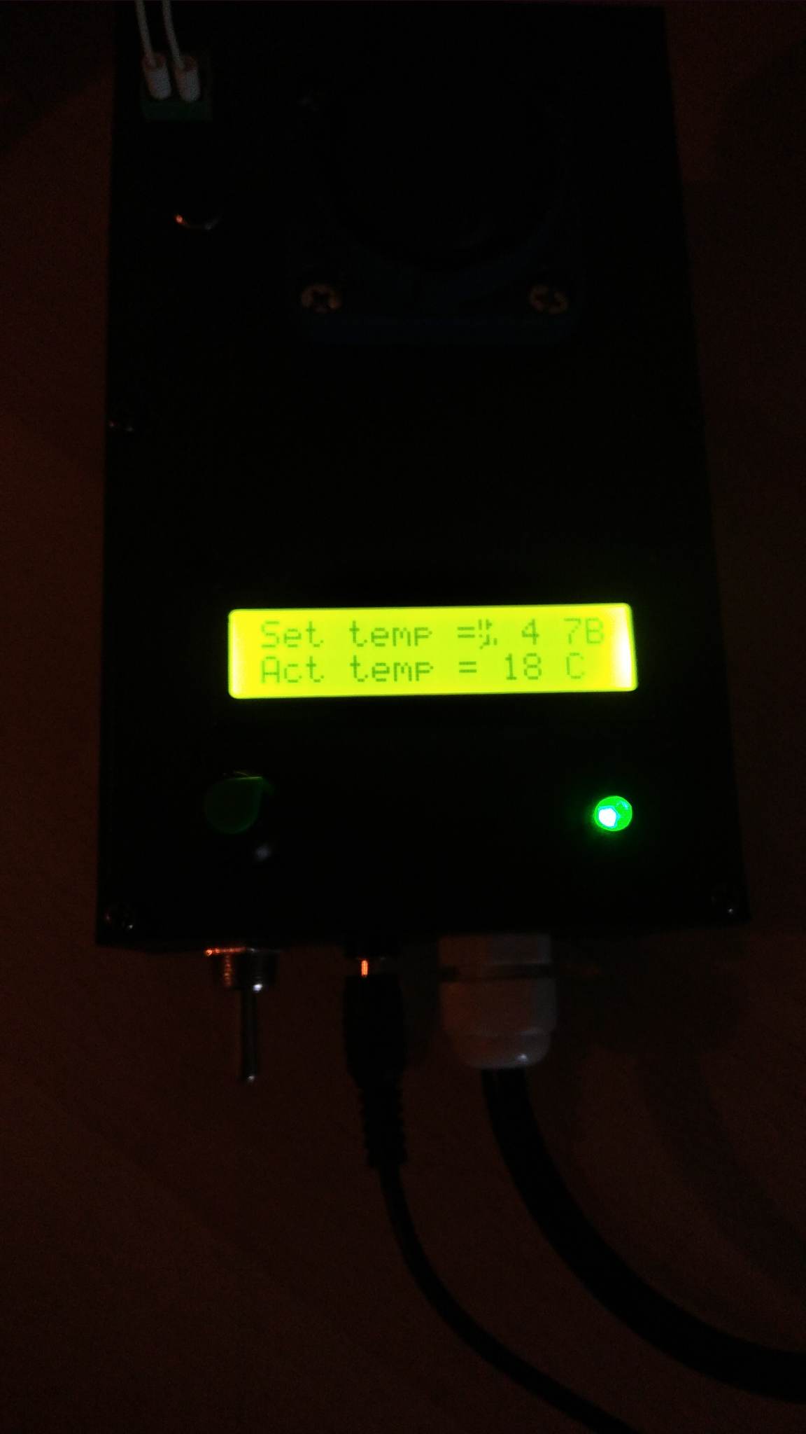
Hy everyone, i am struggling with a 16x2 lcd that keeps showing weird characters on the screen and i wasn't able to figure out the root of the problem.

Weird characters;

The setup is meant to control a cheap soldering iron;

  • using an SSR fotek relay to turn it on/off when it reaches desired temperature
  • arduino nano as the mcu
  • potentiometer to set the desired temperature
  • 16x2 LCD screen
  • a green led that is wired to the relay input to show if it gets signal
  • an input wire that goes through the relay to a socket for the soldering iron
  • an 100k potentiometer from an ender 3 pro, placed inside the tip of the iron where a have drilled a hole, it's wires goes from inside to the mains plug, tied with tape to the 230v cable
  • a 5.5v 3A socket psu that power the whole setup, arduino directly on 5v
  • a switch for mains power cable that goes to the socket

At first i was using a wall 5v phone charger to power the setup wich was placed inside the enclosure with all the other components, my thoughts were that there is some sort of EMI that corrupts the data sent to the screen, caused by electronics inside the SSR, mains voltage wires that goes to the socket wich pass near the 5v arduino wires, noise caused by the transformer of the psu, and the screen placed right on top of these.

I have changed the psu with the one mentioned before, that sits outside the enclosure and delivers power through a round plug from wich there are some short wires that goes to the arduino 5v pin, potentiometer, screen..
The problem still persists but it doesn't happen right away, only after a few seconds/minutes when it starts showing weird characters and even end up being blank.

The solders of the screen and the i2C adapter are all good, i have added a ~47uF cap on the wires that power all of the things mentioned above. Another thing is that when i have chosen the resistor for the thermistor voltage divider, with a smaller one i got more problems with the screen than with a bigger one 6.6kohm that is now on the circuit.

I have thought that there is to much consumption from the Arduino nano and it can't handle all the components some times the green led shows that the setup works fine even it the screen doesn't but sometimes it all freezes and adjusting the potentiometer does nothing, the led + relay remaining on and the screen messed up.

Lately i have tried to power through the usb port on the arduino from a laptop that delivers about 4.5V and i didn't got much problems so far, the screen is not that bright. So why would powering to the 5v of the Arduino cause problems with the screen?

Here is the code;

#include <LiquidCrystal_I2C.h>
#include <math.h>

//A4(22) SDA
//A5(21) SCL

//A6(20) POTENTIOMETER
//D13 RELAY
//A0 THERMISTOR

int ThermistorPin = A0, releu = 13, pot = 20;
int inputTemp;
boolean bol = true;

int Vo, Tc;
float R1 = 6660; //6.66 kohm
float logR2, R2, T;
float c1 = 1.053121362e-3, c2 = 2.019510677e-4, c3 = 0.05061621614e-7;

LiquidCrystal_I2C lcd(0x27,16,2);

float floatMap(int x, float in_min, float in_max, float out_min, float out_max) {
  return ((float)x - in_min) * (out_max - out_min) / (in_max - in_min) + out_min;
}

void temp(int set, int act){
  R2 = R1 * (1023.0 / (float)act - 1.0);
  logR2 = log(R2);
  T = (1.0 / (c1 + c2*logR2 + c3*logR2*logR2*logR2));
  Tc = round(T - 273.15);
 // Tf = (Tc * 9.0)/ 5.0 + 32.0;
 if(Tc>0){
  lcd.setCursor(0,0);
  lcd.print("Set temp = ");
  lcd.print(set);   
  lcd.print(" C");
  //Serial.println("Set temp = ");
  //Serial.print(maped);   
  //Serial.println(" C");

  lcd.setCursor(0,1);
  lcd.print("Act temp = ");
  lcd.print(Tc);   
  lcd.print(" C");
  //Serial.println("Act temp = ");
  //Serial.print(Tc);   
  //Serial.println(" C");
 }
}

void action(int set){
    if(Tc<0){
    digitalWrite(releu, LOW);
    lcd.clear();
    lcd.setCursor(0,0);
    lcd.print("Err termistor!");
    delay(1000);
    }else{
      if((Tc-1)>set){
        digitalWrite(releu,LOW);
        //Serial.println("LOW");
        } else if(Tc<set-4){
        digitalWrite(releu,HIGH);
        //Serial.println("HIGH");
      }
    }
}

void smooth(int& set, int& act){
  float Setvalue = 0.0;
  float Actvalue = 0.0; 
  float numReadings = 30.0;

  for (int i = 0; i < int(numReadings); i++){
    // Read light sensor data.
    Setvalue = Setvalue + analogRead(pot);
    Actvalue = Actvalue + analogRead(ThermistorPin);

    // 1ms pause adds more stability between reads.
    delay(1);
  }

  // Take an average of all the readings.
   Setvalue = Setvalue / numReadings;
   Actvalue = Actvalue / numReadings;

   set = round(Setvalue);
   act = round(Actvalue);
}

void setup() {
  pinMode(ThermistorPin, INPUT);
  pinMode(releu, OUTPUT);
  digitalWrite(releu, LOW);
  pinMode(pot, INPUT);
  lcd.begin();       
  lcd.backlight();      // Make sure backlight is on
  Serial.begin(9600);
}

void loop() {

  smooth(inputTemp, Vo);
  float maped = floatMap(inputTemp, 0.0, 1023.0, 300.0, 0.0);
  int setTemperature = round(maped);
  temp(setTemperature, Vo);
  action(setTemperature);

  delay(1000);
}

Code explanation;

I had problems with the analog readings from the potentiometer and the thermistor fluctuating with a few degrees so i made a smooth function to get the average over a couple of reading then mapped the value from 0-1023 to 0-300 and rounded the result. Now i get a very constant reading.

Then i have a function to calculate the soldering iron temperature based on the thermistor reading, using Steinhart's ecuation for wich i have used an online calculator to get the PID values by measuring the resistance of the thermistor at different temperatures.

It has being said that i have to use a resistor for the voltage divider about the same resistance as the thermistor at the temperature i will be using it. This case around 200 C and i got a pretty low value wich a don't remember, betwenn 100-2000 ohm i believe but when i tried using a resistor that low, the screen got worse so i ended up using a 6.66 kohm one.

The last function turn the relay on/off if the read temp is lower/higher within the specified amount, from the set temperature.

Here is a drawn schematic;
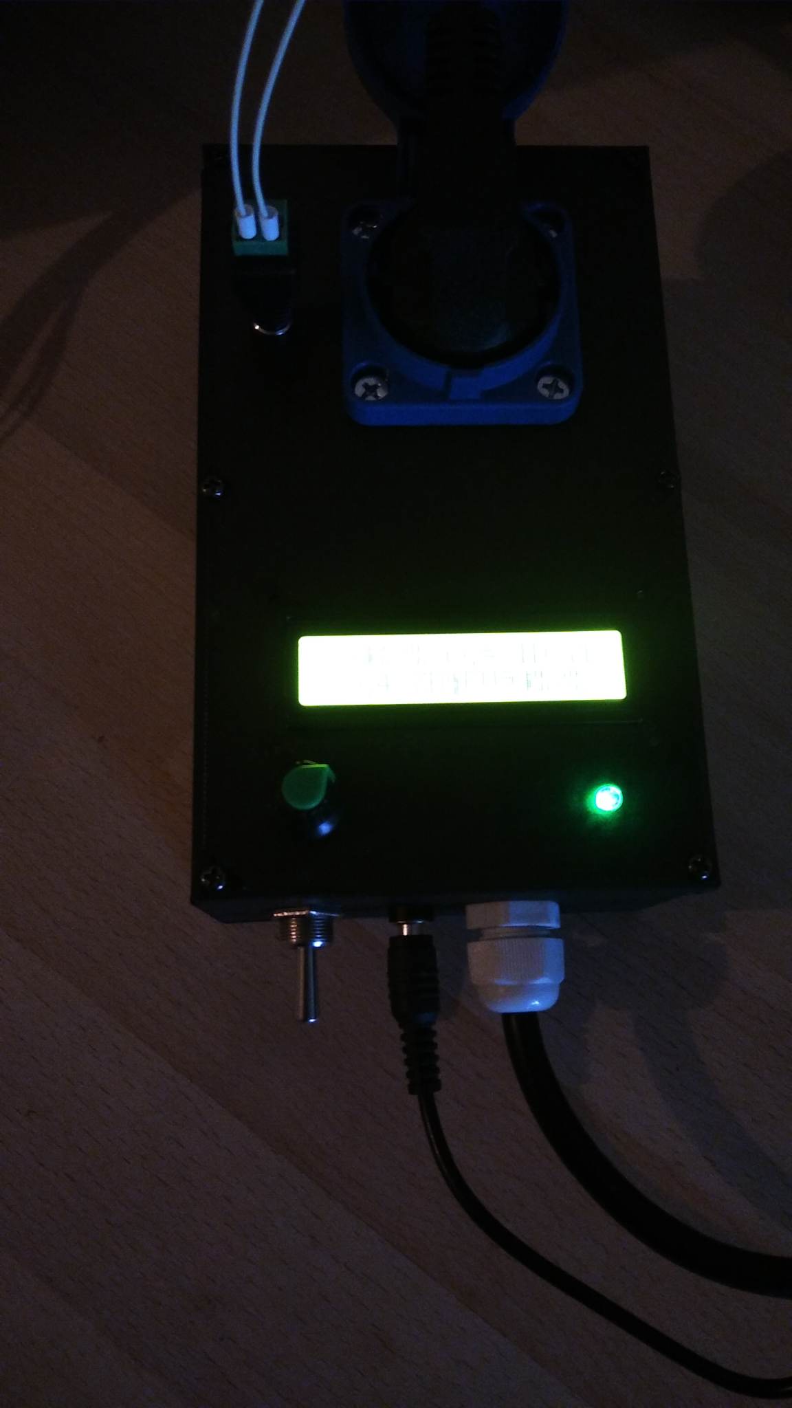
Photos;


I would appreciate any help!
Regards, Alex!

Thanks for code and schematics but can You please clean up the text? Novels make readers skip the post. Drop all failed attempts and stick to the present situation.
Is vreadboard used? Check I2C wires. Is there an intermittent contact?
What is question of now?

Hy thanks for the comment, i don't know what to do anymore to get answers, if i post briefly they say i didn't give enough information, if i say all i can about the setup no one reads..

I forgot to post the inside of the box, i did now but it is messy and it's with the 5v phone charger placed inside instead of the external one but that doesn't make a big difference.

I haven't used breadboards, all connections are soldered to a prototyping board where are placed some screw connectors for all wires wich are also soldered directly at the other end or screwed using ferrules.

The only plug in connections are for the potentiometer and the screen wich have some JST / dupond type connectors from my 3d printer wires that i had lying around but they seem ok, if it works with power through laptop usb then is shouldn't be an issue

If it was to be the conection on the i2c module, scl sda gnd and + then i guess it shouldn't work with laptop either

Nice try on the schematic but it is not what you are showing in the pictures. Please show alll connections, power supply, grounds, etc. Posting links to the hardware items helps all of us if they show technical information. Links to amazon and other similar market places do not have the needed information.

The connections are not number one suspect. However, know that solder moves into the strains in multi strain cables. This makes that area woulnerable.
You have some stiff cables in the box... They might press on some connector and change things when the box is closed.
How do things run with the top off? Touching cables softly could show a weak point.

Intersting, i ran the setup with the box opened when i had the first phone charger psu thinking that the emi could be a problem and i have separated then a little to give some space. It still hapened but not so often from what i remember i could try again but i think it got tired of me opening and closing the lid :slightly_smiling_face:
Still the laptop vs wall psu doesn't influence the inside wiring or moving anything while testing so i am wondering what does powering trough 5v vs usb makes a difference ?

I suppose i can post links if they help but i have some pretty generic parts. What are you refering that is not the same in the drawing ?

Hi, @alex0512343

What happens is that the LCD is only initialized once in setup(), after that we don't need to restart it.
But if in the course of time, for some probable reason of electrical noise, the LCD loses the correct initialization, it starts to show strange characters.
As you use SSR and they generate very fast responses (and possible electrical noise), I suggest you use snubber on the SSR output to the welder.

"Snubber - Wikipedia(shock absorber)%20%C3%A9%20um,very%20r%C3%A1pids%2C%20in%20systems %20mec%C3%A2nicos."

PS: For debug purposes try to reset the LCD from time to time.

1 Like

Ok, i will try to restart it at an interval, i don t really need an ssr wich also takes a lot of space but i don t have a good 5v mechanical relay laying around, a resitor with a capacitor on the 230v in /out contacts but what value shoud they be?
The thing is that i have considered the ssr to make noise so i have tested with it off also but the screen still messed up after some time

Minor value of it but the I2C cables are missing.

One theory: The USB power supply is more resistent to mains moise then the charger. The SSR switches mains and that might have an influence on a not so good charger....

**Edit: **
Run the setup but make sure no switching is done in the SSR! Set parameters to values that don't come in play.

please check the hello world example of your library.

It might be that you need a lcd.init() instead of the lcd.begin().
use exactly what you see in the example.

Sorry for scl sda, they are wired to nano's predifined
//A4(22) SDA
//A5(21) SCL

So are you saying that the ssr induces noise in the mains voltage that is switching wich will influence the mains input of the 5v psu? For wich the laptop is a separated source? I might try using some ferrite cores somewhere

I remember that i have tried in all combinations, with mains cable pluged/unpluged, switch on/off, potentiometer set low so that ssr won t be on and i got pretty much the same results, after a while it messes up. I left it powered by usb with ssr off and it didn t corupted even after some time but the screen was not that bright since it has only 4.5 instead of 5.5v of the wall psu and i have set the potentiometer on the screen for brigthness for the 5.5v one.

Edit, or are you referring that the input pins of the ssr, - and + 5v dc conduct noise in the arduino digital output pins and directs it to the common 5v psu for all the stuff ?. This sounds more plausible than the other wich i don't get how it could induce noise in the mains since it is just turning it on/off

I have tried with .init but i get an error saying that is not recognized

'class LiquidCrystal_I2C' has no member named 'init'

The HelloWorld example is like this, same as i did.
Although i am printing on the screen within 1 sec intervals using lcd.setCursor(0,0); lcd.print("Set temp = "); wich just replaces the characters instead of wiping the whole screen with lcd.clear(); so that it won't take that much time to complete and overstress the screen. For this i will get double C C on temps that are 1 or 2 digits when i come from 300 C below and won't erase that C just replace the characters to it's left.
Ex something similar;

Set temp = 300 C
Set temp = 3 C C

#include <Wire.h> 
#include <LiquidCrystal_I2C.h>

// Set the LCD address to 0x27 for a 16 chars and 2 line display
LiquidCrystal_I2C lcd(0x27, 16, 2);

void setup()
{
	// initialize the LCD
	lcd.begin();

	// Turn on the blacklight and print a message.
	lcd.backlight();
	lcd.print("Hello, world!");
}

void loop()
{
	// Do nothing here...
}

Depending on the kind of load powered by mains it's surely possible. Just the turn On/turn Off is were current rushes, voltage spikes can be created.

The common thing for trouble is when the charger is used. Try using another charger. I've not tried to calculate the total current consumed by Your build. Chargers have limits.....

Reinitializing the LCD is not be needed in a healthy build. Kill the source of the trouble, not the symptoms.

1 Like

Your LCD char set has Katagana RA and ME with a DAKUTEN which softens a palatial aspiration (k >> g).


I think i can try to adjust a usb cable to power with the wall psu trough it instead of 5v pin to see what happens. It s a soldering iron wich has an internal winding of wire so i think it s resistive load, adding a snubber (cap + resistor) migth help as pointed out but idk the values that i need

But also the problem happenes with no switching of the ssr that was powered off also.
The first charger might have a limit and the second psu is a cheap 5v 3A psu so it might cause problems..

Thanks for pointing this out, i don t quite understand what does it mean tho
Am i not sending corect bytes, is serial baud rate definition interfering or should i modify the i2c address? Sometimes i get a blank screen after a while of this weird one

Can you create a custom character of "all 1s" to see if a bit or line is held low or high, then a custom character of all zeroes, the an alternating one-zero, then alternating zero-one.

Also, there is a way to use an old ASCII character set, but that escapes me.

Something inside the LCD is overheating. Do a physical inspection.

That can actually be due to higher voltage of the psu. I have just tried to power also from the laptop usb but on the 5v pin of nano and it also works and it is brigther that via usb port on nano. It shouldn t heat after few seconds 10, 20 s maybe