Hey,
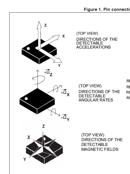
I'm trying to compute the orientation of my Arduino Nano 33 BLE using it's on-chip LSM9DS1 IMU. I try to use the Arduino Madgwick Filter Library. I update the filter using the values which I get from the accelerometer, gyroscope and magnetometer using the Arduino LSM9DS1 Library.
However, when rotating the Nano (e.g. 45° pitch) it takes a pretty long time until the measured euler angles from the Madgwick Filter settle at the given angle.
So generally speaking, I'm searching for a way to improve the response time of the Madgwick Filter or to fix my implementation in case there is something I'm totally doing wrong here.
Here is my code:
#include <MadgwickAHRS.h>
#include <Arduino_LSM9DS1.h>
float gForceX, gForceY, gForceZ;
float rateRoll, ratePitch, rateYaw;
float mX, mY, mZ;
float gyroXOffset, gyroYOffset, gyroZOffset;
float accXOffset, accYOffset, accZOffset;
float magXOffset, magYOffset, magZOffset;
Madgwick filter;
unsigned long microsPerReading, microsPrevious;
unsigned long microsNow;
void calibrate();
void setup() {
Serial.begin(9600);
while (!Serial);
gyroXOffset = gyroYOffset = gyroZOffset = 0;
accXOffset = accYOffset = accZOffset = 0;
magXOffset = magYOffset = magZOffset = 0;
if (!IMU.begin()) {
Serial.println("Failed to initialize IMU.");
while (true); // Stop execution
}
calibrate();
filter.begin(119);
Serial.println(IMU.accelerationSampleRate());
Serial.println(IMU.gyroscopeSampleRate());
Serial.println(IMU.magneticFieldSampleRate());
microsPerReading = 1000000 / 119;
microsPrevious = micros();
}
void loop() {
microsNow = micros();
if (microsNow - microsPrevious >= microsPerReading) {
// put your main code here, to run repeatedly:
IMU.readAcceleration(gForceX, gForceY, gForceZ);
IMU.readGyroscope(rateRoll, ratePitch, rateYaw);
IMU.readMagneticField(mX, mY, mZ);
gForceX -= accXOffset;
gForceY -= accYOffset;
gForceZ -= accZOffset;
rateRoll -= gyroXOffset;
ratePitch -= gyroYOffset;
rateYaw -= gyroZOffset;
mX -= magXOffset;
mY -= magYOffset;
mZ -= magZOffset;
filter.update(rateRoll, ratePitch, rateYaw, gForceX, gForceY, gForceZ, mX, mY, mZ);
Serial.print(filter.getRoll());
Serial.print(",");
Serial.print(filter.getPitch());
Serial.print(",");
Serial.println(filter.getYaw());
microsPrevious = microsPrevious + microsPerReading;
}
}
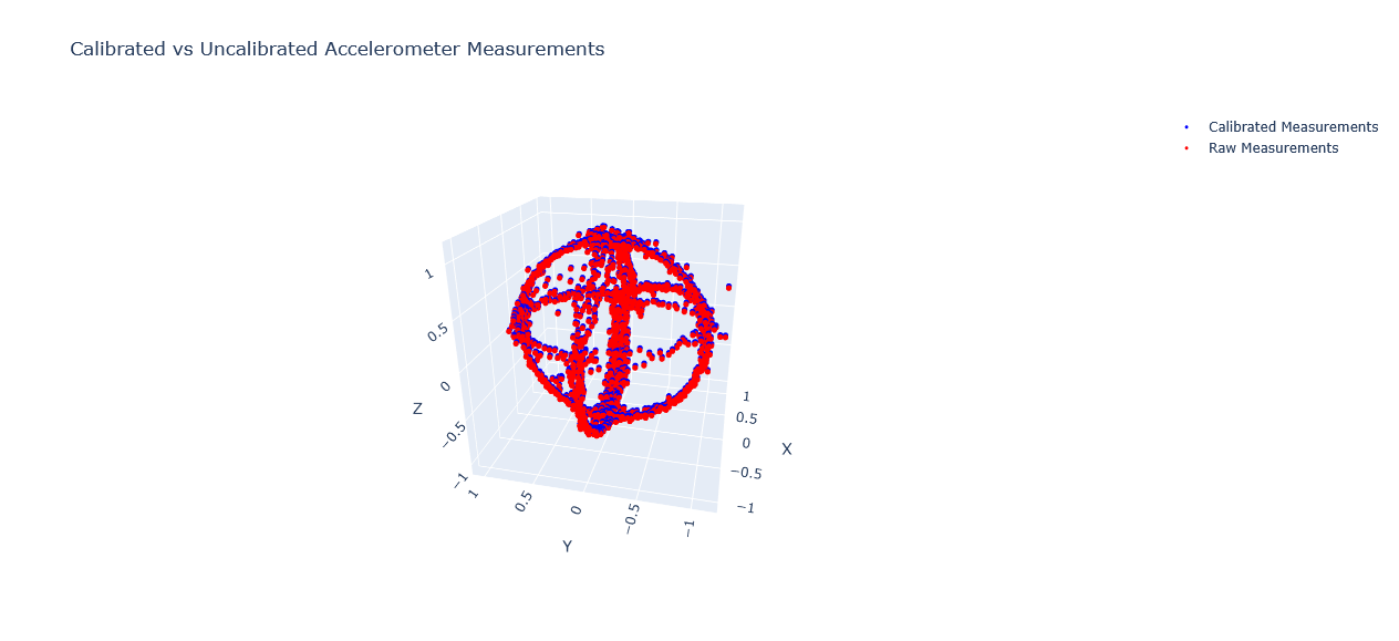
void calibrate() {
Serial.println("Calibrating Gyroscope ...");
int numSamples = 2000;
for (int i = 0; i < numSamples; i++) {
IMU.readGyroscope(rateRoll, ratePitch, rateYaw);
gyroXOffset += rateRoll;
gyroYOffset += ratePitch;
gyroZOffset += rateYaw;
delay(1);
}
gyroXOffset /= numSamples;
gyroYOffset /= numSamples;
gyroZOffset /= numSamples;
Serial.println("Gyroscope Calibration completed.");
Serial.println("Calibrating Accelerometer ...");
for (int j = 0; j < numSamples; j++) {
IMU.readAcceleration(gForceX, gForceY, gForceZ);
accXOffset += gForceX;
accYOffset += gForceY;
accZOffset += gForceZ;
delay(1);
}
accXOffset /= numSamples;
accYOffset /= numSamples;
accZOffset = (accZOffset / numSamples) - 1;
Serial.println("Accelerometer Calibration completed.");
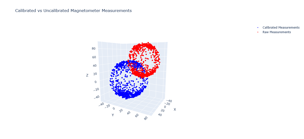
Serial.println("Calibrating Magnetometer ...");
numSamples = 5000;
float mMinX, mMinY, mMinZ;
float mMaxX, mMaxY, mMaxZ;
mMinX = mMinY = mMinZ = 1e6;
mMaxX = mMaxY = mMaxZ = -1e6;
for (int k = 0; k < numSamples; k++) {
IMU.readMagneticField(mX, mY, mZ);
if (mX < mMinX) mMinX = mX;
if (mY < mMinY) mMinY = mY;
if (mZ < mMinZ) mMinZ = mZ;
if (mX > mMaxX) mMaxX = mX;
if (mY > mMaxY) mMaxY = mY;
if (mZ > mMaxZ) mMaxZ = mZ;
delay(1);
}
magXOffset = (mMinX + mMaxX) / 2;
magYOffset = (mMinY + mMaxY) / 2;
magZOffset = (mMinZ + mMaxZ) / 2;
Serial.println("Magnetometer calibration completed.");
}