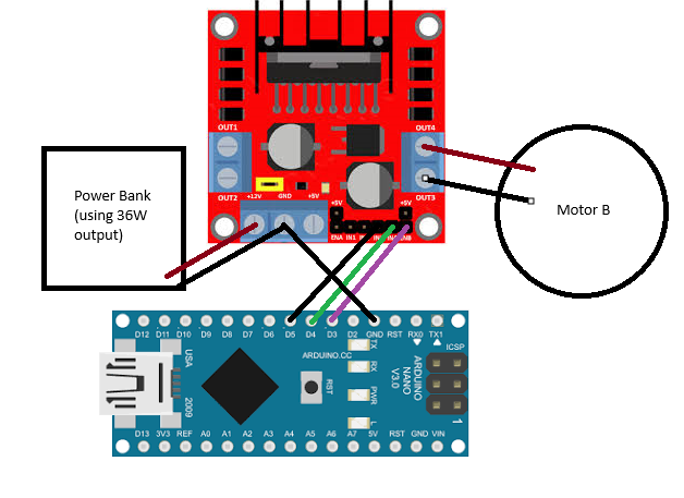
I have an Arduino nano and an L298n motor driver. When I write the code for a motor connected to the ENA side of the motor driver and then upload it, no errors show and it seems like the upload was successful. Although, the motor just won't move. I'm connecting the motor driver through a 36W USB output. The light on the L298n is turned on and so is on the Arduino. All help appreciated. If this is not the correct place to post this please tell me which topic this should go in.
Based on Your post, where do You expect helpers to find the problem? Using crystal balls?
Why didn't You read How to get the best out of this forum - Development Tools / IDE 1.x - Arduino Forum before posting?
Shucks my crystal ball has a crack running through your schematic. Post your annotated schematic showing exactly how you have wired it. Show all power sources, power, ground and any other hardware items connected to the circuit.
I'm not using an official Arduino Nano board, I bought this one from Ebay: ATmega328P Nano Type-C-Controller Board Soldered Compatible with Arduino Nano V3 | eBay.
The code that I put into the Arduino Nano is:
#define ENA 3 // Enable Motor A (PWM)
#define IN1 8
#define IN2 9
#define IN3 10
#define IN4 11
#define ENB 5 // Enable Motor B (PWM)
void setup() {
pinMode(ENA, OUTPUT);
pinMode(ENB, OUTPUT);
pinMode(IN1, OUTPUT);
pinMode(IN2, OUTPUT);
pinMode(IN3, OUTPUT);
pinMode(IN4, OUTPUT);
}
void loop() {
digitalWrite(IN1, HIGH);
digitalWrite(IN2, LOW);
digitalWrite(IN3, HIGH);
digitalWrite(IN4, LOW);
analogWrite(ENA, 150); // Speed for Motor A
analogWrite(ENB, 150); // Speed for Motor B
delay(3000);
analogWrite(ENA, 0);
analogWrite(ENB, 0);
delay(2000);
}
Heres a model of my wiring:
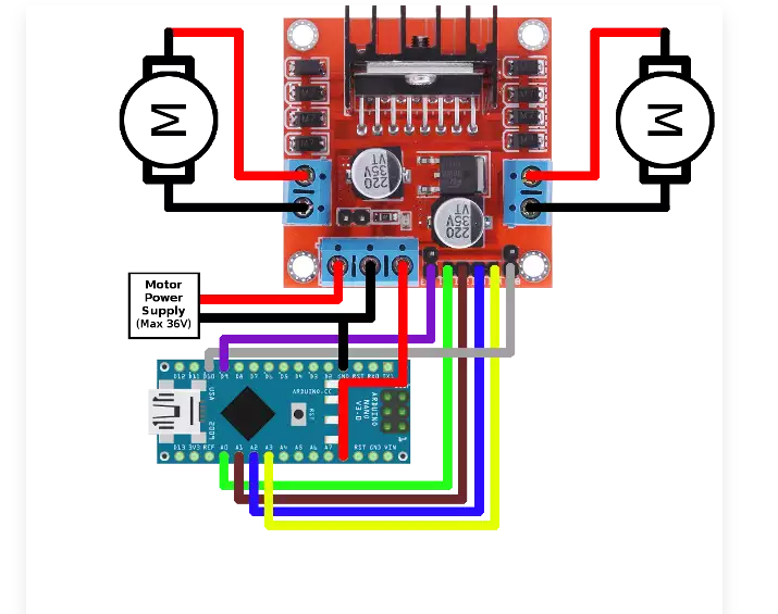

So I connect purple wire to D3, gray wire to D5, green wire goes to D8, and then yellow wire goes to D11? Sorry
Is 5V your motor supply voltage? That's absolute minimum that it might work. But it has big voltage drop, so in case it works, only ~3V arrives to motor. Do they run at that low voltage?
Sorry I do not have parts that look like your picture.
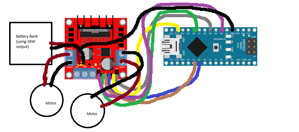
You have wired it incorrectly, twice.
The code must match the wiring.
That wiring still doesn't match your sketch, and what on earth are you doing feeding 12V into the external 5V enable jumper rather than the terminal block?
Did I wire the enable pins wrong?
Oh I saw a video and they were using those pins
I don't believe I can help you any further. Good luck with your project.
Your wiring and your code must agree.
What pins you are using? Stop guessing.
this is my new diagram and wiring

g:
my new code is:
int ENA_PIN = 3;

int IN1_PIN = 4;

int IN2_PIN = 5;
void setup() {

pinMode(ENA_PIN, OUTPUT);

pinMode(IN1_PIN, OUTPUT);

pinMode(IN2_PIN, OUTPUT);
analogWrite(ENA_PIN, 255);

digitalWrite(IN1_PIN, HIGH);

digitalWrite(IN2_PIN, LOW);

}
void loop() {
}


I don't understand, my code variables are matching up to the pins to the arduino, on the arduino Im using D3 for ENA, for IN1 im using D4, and for IN2 im using D5
Un-readable. Make everything clealy readable.
Does it run?
Wait by clearly readable do you mean that the text on the motor driver and Arduino aren't large enough?
Why should I wait? You must make your drawings understandable.