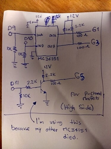
***Edit I attached the images
Hi.
I'm currently working on a Brushless DC Motor Controller with Arduino but I have a problem with a Digital Output. The problem is the following:
I have 6 Digital Outputs to control an Inverter(H Bridge with 3 Arms)
-Image1-
(1,3,5) PWM Outputs for the High Side Mosfets and (2,4,6) Outputs for the Low Side Mosfets.
-image2-
I was measuring the voltages for the High Side Transistor Outputs Gates and they are fine when only they 3 are connected to the board.
If I connect the 6 Outputs to the board, one fails, one from the High Side.
-image3-
For this Test I have no Mosfets connected on the Protoboard
By connect to the Board I mean From Arduino Nano to the Protoboard. And the one that fails is the Transistor at the second image for G5. I will buy another MC34151, but this schematic should work, right?
G1 and G3, measure 11.5V when " input off" and around 7V when "input PWM at ~50%" also G5 measures that when D5, D6 and D7 are not connected to the protoboard.
If I connect D5 to the protoboard everything is still Ok, If i connect D5 and D6, G5 Measures 10, then 7 then 4 then 0, Something like that. If I connect D5, D6 and D7, G5 measures roughly 1.5V.
Any Ideas?
Thank you and sorry for the long post.


