Arduino Nano Every and WS2812B

Hi,
It is my first contact with Arduino (and with building something from electronics by myself), so I probably have lack of knowledge how it should works :wink:

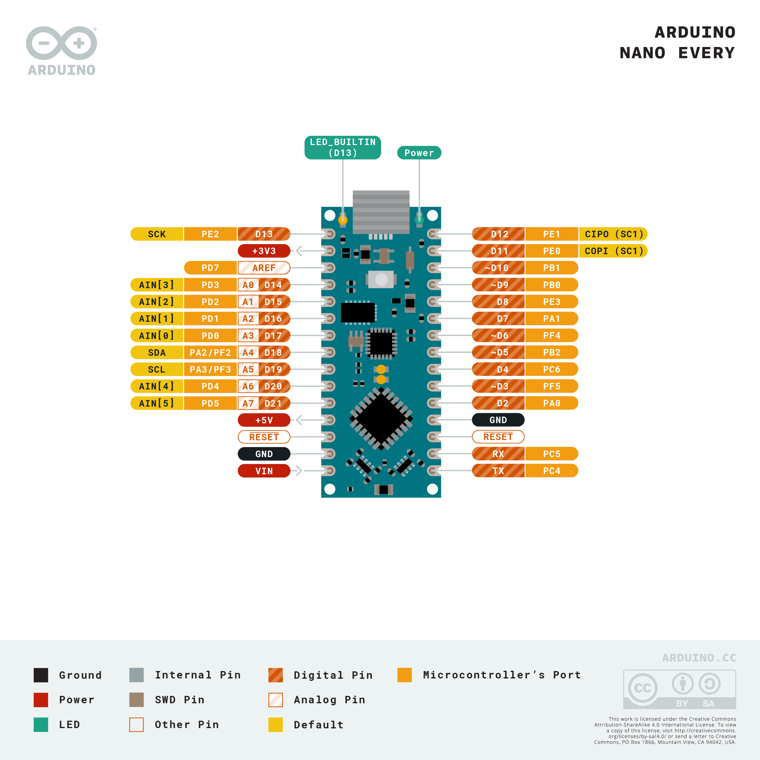
I'm trying to connect my arduino nano every to leds - ws2812b.
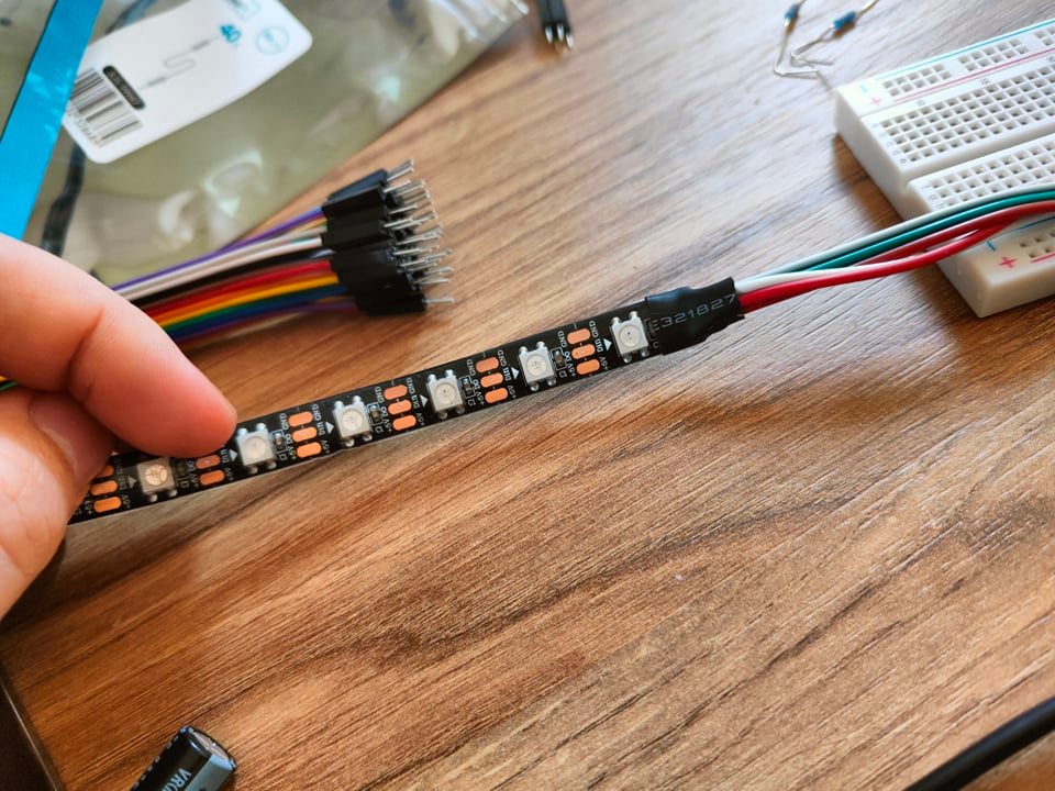
But I'm not able to see any colors. I have attached photo of my solution and source code of my application.

I have found information about problems with FastLeds and Arduino Nano Every.

It looks like it is not supported right now? I was trying to apply fix from one comment, but it looks like those changes are already in library (but I don't understand why issue is not closed? - maybe it is still not working correctly?)

I was trying to fix any code to use leds without FastLeds lib, but I'm not able to find any example :frowning:

I'm appreciate any help.

#include <FastLED.h>
#define LED_PIN 2
#define NUM_LEDS 12

CRGB leds[NUM_LEDS];

void setup() {
  FastLED.addLeds<WS2812B, LED_PIN, RGB>(leds, NUM_LEDS);
  FastLED.setMaxPowerInVoltsAndMilliamps(5, 500);
  FastLED.clear();

}

void loop() {
  leds[0] = CRGB(255, 0, 0);
  leds[1] = CRGB(0, 255, 0);
  leds[2] = CRGB(0, 0, 255);
  FastLED.show();
}

Please post real schematics.

I was trying power from USB, but also I have a separate power supply, and also doesn't work.

I was using this schema: (I'm using pin 2 in my source code, but I was trying evey pin from arduino)

Arduino nano every pinout:
Pinout

That doesn’t look like 330ohm resistor, and why do you even need one?

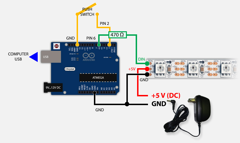
As I understand this resistor is not required, but as I understand he is needed to protect the first did from burning.
When I was preparing I found a few diagrams and in some, they are using 470. (example version with 470

I have bought two resistors and I was trying with both and it didn't help :frowning:

My resistors:

have you tried without any?

The resistor is fine, and a good idea. Just make sure it is 470 or 330 both fine.

Have you tried a different library, like the adafruit library?

Are you sure you have nominated the correct type of strip? RGB, RBGW &c.

Getting that wrong usually means wonky weird colors at wrong positions on the strip.

a7

1 Like

OK, unlikely to be a bad pin, so no need to test l other pins.

If you are worried about the pin, just test it with a regular LED and series current limiting resistor.

a7

@killzone_kid yes and it didn't help :frowning:
@alto777 I think it is ws2812b (shop was selling with that name), but I will attach foto (strip
looks like other photos I have found in internet)
I didn't know about adafruit. I will try!

My strip:

How come? The data sheet only specifies that DIN should be

0.7VDD min for High
0.3VDD max for Low

Wait, the strip has 4 wires right? Are you sure you are connected to Din and not to Dout?

1 Like

@killzone_kid

google it. The resistor is "best practices", as the OP discovered in his research, "to protect the first diode from burning", which is a reasonable lay person's apprehension of the problem.

Having said that I've made dozens of projects without the resistor, but it is an accident waiting to happen, or more accuratley you will comprimise the longevity of the circuit by omitting the resistor.

So now I go to the extra troubel and expense (!) of using one. Always.

a7

Whatever you say, I find it strange there is no mention in the data sheet

Haha, good eye!

There are 5 wires, Vcc and GND are doubled for convenience, but it does look awfully like you've connected to the wrong end of the strip.

Data flow follows the arrows that are on the strip.

a7

1 Like

Stubborn today much? It isn't "whatever [I] say", google it.

And yes, the data sheet makes no mention of this unforuntae fact.

If you looking at the same one I find, it isn't like the greatest data sheet ever written, so just take the grain of salt which is the vast and wide experience of many and use the reisitor without resisting.

:wink:

The sheet doesn't mention the 100 - 1000 uF capacitor that is also a good idea.

a7

Exactly so why the connector is on the out end?

There are 3 wires. I attach a better photo, sorry for that. As I understand these two wires are used when I'm using an external power supply.

The strips I get have nice connectors on the ends so they can be daisy chained into longer strips.

It is obvious mechanically how two strips should be connected. Hard/impossible to get wrong unless you really trying.

But... there is nothing to keep you from playing at the wrong end.

Your picture shows the arrow indicating data flow, it looks like you are talking to the end that wants to talk, not listen.

As I understand these two wires are used when I'm using an external power supply.

That's exactly right.

a7

I’d buy a neopixel ring (well i have one) and try that too to eliminate faulty strip. In the worst case you end up with merchandise for the next project.

Omg :smiley: Thanks :smiley: It was it :smiley: I was connected to the wrong side :frowning: :frowning: I was thinking there is no difference :smiley:

Again, thanks you guys! :slight_smile: