Hi,
I'd like to make a device to drive a car speedometer.
The existing speedometer requires a set number of pulses/mile, but I have wheel speed sensors that output a different value, so I'd like to read an input frequency, apply a correction factor, and output an amended frequency using a Nano.
I need to read an input frequency between zero and around 500Hz, and output zero to around 300Hz.
I've written a sketch that can create a suitable output frequency range if I manually input an input frequency, but when I try and add the <FreqMeasure.h> library, and input a frequency from an external device (An Uno running a signal generator sketch), my conversion maths has no effect
Is a Nano capable of the function that I'm trying to use, or does the nano not have enough timers?
'ant tips would be greatfuly received
#include <FreqMeasure.h>   //NOTE:- Frequency measurment of pin 8 is defined within this library.
float frequency = 0;

const int outputPin = 12; // Use digital pin 12


void setup() {
  pinMode(outputPin, OUTPUT);
  FreqMeasure.begin();

}
double sum=0;
int count=0;


void loop() {

if (FreqMeasure.available()) {
    // average several reading together
    sum = sum + FreqMeasure.read();
    count = count + 1;
    if (count > 5) {
      float frequency_Input = FreqMeasure.countToFrequency(sum / count);

   sum = 0;         //don't forget these
   count = 0;         //don't forget these


float InputToOutputFactor = 0.61;

float frequency = frequency_Input * InputToOutputFactor;
; // Frequency in Hz
    }
if (frequency>41)
{
const long interval = 1000000 / frequency; // Calculate the interval in microseconds
const long halfInterval = interval / 2;
  digitalWrite(outputPin, HIGH);
  delayMicroseconds(halfInterval);
  digitalWrite(outputPin, LOW);
  delayMicroseconds(halfInterval);
}
if (frequency<41)
{
const float interval_2 = 1000 / frequency; // Calculate the interval in milliseconds
const float halfInterval_2 = interval_2/ 2;
  digitalWrite(outputPin, HIGH);
  delay(halfInterval_2);
  digitalWrite(outputPin, LOW);
  delay(halfInterval_2);

}

}
}`Use code tags to format code for the forum`
type or paste code here
500Hz slow enough that you could probably do it by testing the input pin in code with digitalRead(). Otherwise, PulseIn should work. Although I think PulseIn() is blocking, so no other code will execute while it's running. Make sure that FreqMeasure doesn't have that same problem!
What is the exact ratio of the old frequency to the new frequency? If a whole number, there will be cases where the signals will overlap and will be difficult to program for. Even then, there are very likely to be some points that will line up and cause glitches.
I don't know the exact factor that I need to modify the frequency by, and was hoping to fine tune the multiplication factor by road testing and comparison with recorded GPS speeds once I have something close working.
I thought I was close, but then, when I added these lines:-
float InputToOutputFactor = 0.61;

float frequency = frequency_Input * InputToOutputFactor;`
The scaling factor "InputToOutputFactor" has no effect on my output frequency
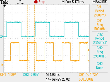
I've tested your code using an Arduino Uno R3, as I don't have a Nano available.
I fed a square wave from a function generator in to pin8, and monitored the output on pin 12 using an oscilloscope.
The code seems to give a narrow pulse around 20µs wide at the same frequency as the input.
As part of my investigation, I removed the part of the code that generates the output frequency and replaced it with a section that took the output high, printed the values of 'frequency_Input' and 'frequency' then took the output low again.
Here are the results:
I'm doing some tests to see if I can use interrupts to measure the period, but generate the output using your method of taking the output high, delay for half the new period, take the output low,delay for half the new period.
I'll let you know what I find.
I rejected that method on the other topic as there are errors that get worse as the frequency goes up - they wanted to work up to 15kHz.
Thank you for your replies so far.
After a little research via one of the listed links, I found a link to another project that included some less elaborate code than my original attempt, not actually measuring frequency, but, as suggested, period, then outputting suitably modified period.
This works well up to an input frequency of around 400Hz, but not above that frequency.
Ideally, I'd like it to work upto around 500Hz.
Is there something that I could do to the following code, to allow an input of 500Hz?
//1986 Porsche 944 Turbo Speedometer CalibratorcurrentSpeed
//Public Domain
//raw 944 transmission sensor signal must be processed by external schmitt trigger
//Schmitt trigger should bypass filer and pull-up resistor
//Use LM2940-10 with decoupling caps per datasheet to power Arduino in automotive setting
//Arduino Pin 7 supplies modified signal for speedometer

 const int debounce = 2500;
 const int speedometerPin = 7;
 const int sensorPin = 3;
 int pulseState = LOW;

volatile unsigned long currentMicros = 0;
volatile unsigned long previousMicros= 0;
volatile unsigned long currentSpeed = 0;
volatile unsigned long previousSpeed = 0;
volatile unsigned long interval = 0;
unsigned long modInterval = 0;

float calFactor = .61;   // decrease to slow down speedometer
                                     // calFactor of 1 makes no change to speedometer

void setup()
{
pinMode (13, OUTPUT);
pinMode(speedometerPin, OUTPUT);
pinMode(sensorPin, INPUT);
digitalWrite (sensorPin, HIGH);
attachInterrupt (1, iSr, FALLING);

}

void loop()

{

  noInterrupts();

  modInterval=interval;

  interrupts();

  currentMicros = micros();

  if (currentMicros-previousSpeed<1000000)

  {

   if (currentMicros - previousMicros>((modInterval/2)/calFactor))

       { previousMicros = currentMicros;

        if (pulseState == LOW) pulseState = HIGH; else pulseState = LOW;

        digitalWrite(13, pulseState);         //to blink onboard LED

        digitalWrite(speedometerPin, pulseState);

        }

   }

}


void iSr()

{

  currentSpeed=micros();

  if (digitalRead(sensorPin)==LOW)

     {

        if ((currentSpeed - previousSpeed) > debounce)

           {

            interval = currentSpeed - previousSpeed;

            previousSpeed=currentSpeed;

           }

      }

}