Arduino nano Tx and Rx using NRF24 recieve issue

Hello fellow makers and coders, I'm new here. and need some extra help.

I have been working on getting an Arduino Nano RP2040 Connect with NRF24 to connect with an Arduino Uno or Arduino Nano with matching NRF24. Ive tried the Radiohead, RF24, RF24Network and RF24_G. Ive only just gotten RF24_G to work with the Nano RP2040. I have combined some of the example codes in attempt to get a transceiver working.

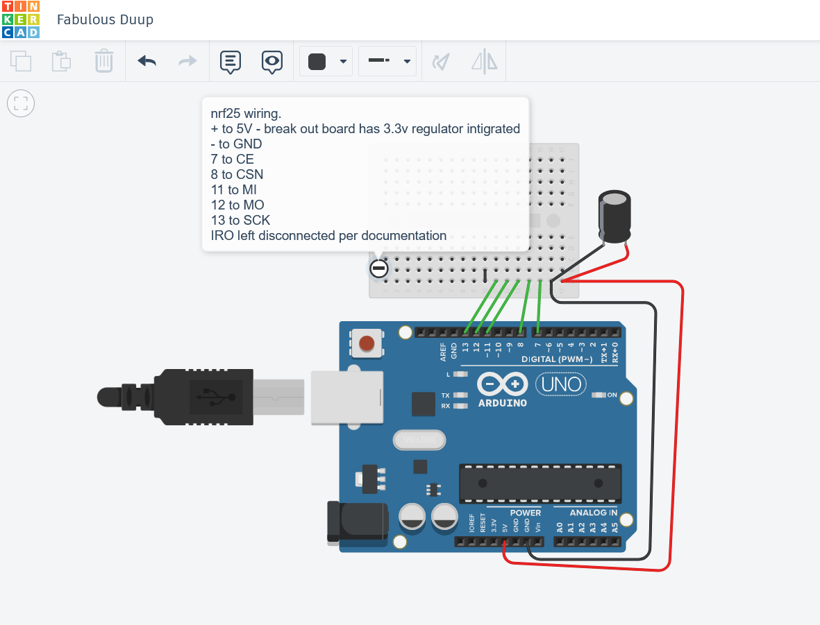
For problem solving purposes: I'm using a windows 11 gaming laptop, Arduino IDE 2.0, and all libraries on their latest updates as of 4/7/2025. All hardware, assume connections are all correct. I'm using jumper wires and breadboard (for the nano). power through usb. I have 2 18650x2 battery packs with buck converters dialed down to 5v that I can use.

#include <rf24g.h>

struct controls {
  int ch1;
  int ch2;
};

RF24_G* radio = nullptr;

void setup() {
  Serial.begin(9600);
  while (!Serial);
  Serial.println("Starting");
  delay(100);
    static RF24_G _radio(0, 7, 8);
  radio = &_radio;

  radio->setChannel(120);
}

void loop() {
  controls data = {12, 220};
  packet send;
  send.setAddress(2);  // Destination = 2
  send.addPayload(&data, sizeof(data));

  Serial.print("Sending to address: ");
  Serial.println(send.getAddress());
  Serial.print("ch1: ");
  Serial.print(data.ch1);
  Serial.print("  ch2: ");
  Serial.println(data.ch2);

  bool success = radio->write(&send);  // ✅ Proper write
  if (success) {
    Serial.println("Data sent");
  } else {
    Serial.println("Send Failed!!");
  }

  delay(1000);
}

In the serial monitor I get:
Sending to address: 2
11:07:38.691 -> ch1: 12 ch2: 220
11:07:38.691 -> writing to this address: 14
11:07:38.861 -> Send Failed!!

On the Arduino Uno I have set up as receiver I have the code:

#include <rf24g.h>

struct controls {
  int ch1;
  int ch2;
};

RF24_G* radio = nullptr;

void setup() {
    Serial.begin(9600);
  while (!Serial);
  Serial.println("Starting");
  delay(100);
    static RF24_G _radio(2, 7, 8);
    radio = &_radio;
    radio->setChannel(120);

}

void loop() {
  controls data;

  packet getdata;
if (radio->available()) {
  Serial.println("packet recieved");
  radio->read(&getdata);
  getdata.readPayload(&data, sizeof(data));
  // data = {12, 220}; // test data variable
  Serial.print("ch1: ");
  Serial.println(data.ch1);
  Serial.print("ch2: ");
  Serial.println(data.ch2);
  Serial.println(sizeof(data));
  delay(1000);
}else{
  Serial.println("Failed to recieve");
  delay(1000);
}
  // Serial.println(radio->available());

  
}

In serial monitor I get:
11:07:30.751 -> reading from to this address: 14
11:07:30.786 -> reading from to this address: 15
11:07:30.819 -> reading from to this address: 17
11:07:30.851 -> reading from to this address: 18
11:07:30.884 -> reading from to this address: 19
11:07:30.917 -> Failed to recieve
11:07:31.860 -> Failed to recieve (this continues looping)

xxxxxxxxxxx
According to chatgtp, there may be an error in the rf24-g library where the write to and read from addresses are calculated. I'm not sure how to contact the person who made the library to ask so I'm asking the community.

My next steps to the project is to connect a couple joysticks to the Tx along with a few switches to make at least a 6 channel remote control. I plan to connect a screen of some sort and have some info printed to it such as battery voltage, time running, low battery alarm and things like that. on the Rx side I want to get an adafruit 16 servo pwm board to work for a quadruped robot project.

Thank you all in advance!

Please explain this and post an annotated schematic of what you have built, be sure to show all power sources, grounds and note any wires over 10"/25cm in length.

How far apart are the transmitter and receiver from each other?

I do not that is why I am asking for an annotated schematic.

Um.... Ive never done a cad schematic before this and this was my first time using tinkercad for a wiring thing. they didnt have an NRF25 board so I improvised.

So to answer your questions, right now I have just the NRF25 and Arduino hooked up. capacitor bridging the + and GND at the NRF24 break out board (as recommended by documentation and users.) I am using 6 inch male to female pin jumper wires. the only long wires are the usb cables going from the arduinos to my laptop. the transmitter and receivers are about 3 ft apart

for the first quoted part. (After I get the transmit and receive issue solved) I plan to use one of the arduino as an RC transmitter by adding 2 X/Y/Btn game controller joysticks (4 pins + 1 ground each) using Analog pins for X/Y and a Digital pin for the button. then use 1 or 2 pins for simple on/of switches as inputs. Similar to the arduino RC videos from HowToMechatronics and other youtube channels. Problem is alot of those videos are over4 years old and when trying to use their code and copy verbatim the steps there were several issues with libraries and syntax errors.

As for the second comment, I dont know how to make a wiring diagram through cad nor do I really have the tools to do so. Ive checked and rechecked, unplugged everything and started over with a different set of jumper wires multiple times. and I really didnt want to get into the tech support question "Have you tried unplugging it, waiting and plugging it back in?" lol I'm really good at making things without microchips work. often it dont look purity but... lol I'm a novice when it comes to codeing but I'm trying to learn. I'm not great with cad (in my opinion). but I can make 3d printed parts that fit snugly. And I'm signed up for a 2 year mechanical design degree starting fall so that may help.... and now I'm rambling..

But hopefully with the above you can assist me.
Thank you,

Using the Arduino as a power supply is not a good idea.

Power Stability Issues with RF24 Radio Modules

As described in the RF24 Common Issues Guide, radio modules, especially the PA+LNA versions, are highly reliant on a stable power source. The 3.3V output from Arduino is not stable enough for these modules in many applications. While they may work with an inadequate power supply, you may experience lost packets or reduced reception compared to modules powered by a more stable source.

Symptoms of Power Issues:

  • Radio module performance may improve when touched, indicating power stability issues.
  • These issues are often caused by the absence of a capacitor, a common cost-saving omission by some manufacturers.

Temporary Patch :

  • Add Capacitors: Place capacitors close to the VCC and GND pins of the radio module. A 10uF capacitor is usually sufficient, but the exact value can depend on your circuit layout.
  • Use Low ESR Capacitors: Capacitors with low Equivalent Series Resistance (ESR) are recommended, as they provide better power stability and performance.

Adding the appropriate capacitors can greatly improve the reliability of your RF24 module by ensuring a stable power supply, thus minimizing packet loss and enhancing overall performance. A separate power supply for the radios is the best solution.

Like I mentioned in the picture I already added capacitors to the transmitter and receiver. I also note I mentioned I have a couple 2 cell 18650 battery packs with 5V buck converters I can use if needed. I'll try this evening again powering the NRF24's with those.

Question remains with the code, what debugging could I add to try and get them to talk. or using the same libraries is there a simple code to see if A will talk to B or something. I've been using ChatGTP to troubleshoot this code for the last month and i end up getting in the same loop of try this , try that, try this again, try that again. I get frustrated shut off the computer and go to bed. Thats why I asked for help here. hopeing someone else has gotten these to work with the same equipment.

Your picture does not convey the information needed to resolve your problem. An annotated schematic is needed. You can draw it by hand but it must be clear and legible. Plan on separate power supplies for the radios.