I am using Keystudion Uno and it says on their sites that the current output is 20mA
https://wiki.keyestudio.com/Ks0001_keyestudio_UNO_R3_BOARD
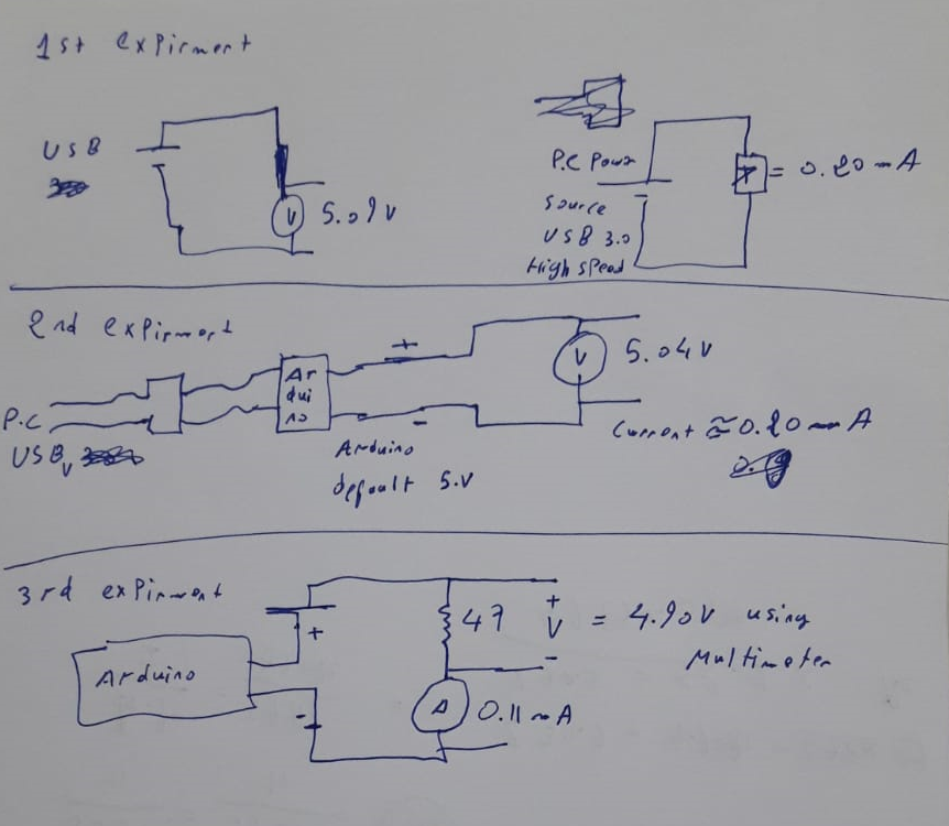
I have measured the Keystudion Uno supply power and Communication cable without plugging it into the Keystudion Uno yet, and gave me a reading of 5.09 V with 0.19 mA.
Then I plugged in my Keystudion Uno cable to theKeystudion Uno and I measured the Default 5V output with my digital multi-meter(UNI-t UT50C), it gave a reading of 5.04v And Current of 0.19mA
Last thing, I hooked a small resistor of 47 Ohm in series with the Arduino 5v Terminal, the Multi-meter shows a reading of 4.90v and Current of 0.11 mA
What I am trying to do is to find out where the 0.14V was dropped. I understand that Multimeter has an Internal resistance(Which I am trying to calculate). Is it possible that Keystudion Uno5v output source has also an Internal Resistance, if so (which I think) how can I Calculate it ?
Also why there was a voltage drop of 0.05 between 5.09v and 5.04v ? where that voltage has gone ? Thanks
How did you measure the current? Please draw it. What was the power source? PC? External power supply (e.g. wall wart) connected to USB?
I am measuring the current using a multi-meter and the power supply is a USB cable from a P.C Version 3.0
I forgot to mention that I am using Keystudion Uno and it says on their sites that the current output is 20mA
https://wiki.keyestudio.com/Ks0001_keyestudio_UNO_R3_BOARD
Hello ak,
Regarding your schematics,
1st experiment
Left hand schematic: looks perfectly reasonable and correct
Right hand schematic: You can't measure current like that. Assuming your meter is set to current you are shorting out the power supply. Many / most / all multimeters has fuses in the current circuit, it is likely you have blown the fuse and will have to replace it.
2nd experiment
I am not clear where you are measuring, but assuming on the 5V pin and the ground pin: that's fine for measuring voltage but if you have then switched your meter to current you are shorting out the 5V. It is probably in current limit. Again, you can't measure the current like that and again check the fuse in your meter.
3rd experiment
I don't understand what you are trying to do. By putting a 47 Ohm resistor in series with the Arduino you are limiting the current to not more than 5 / 47 = 106mA.
You measure current by breaking one of the wires between the supply and the load and inserting your meter in series. You can't measure the 'current' of a power supply by just sticking your meter across it, you are shorting it out. What is the resistor for?
++Karma; // For experimenting and asking questions, generally trying to learn and posting your images correctly. If only all new folk here did that!
The 20mA output current refers to what each GPIO pin can handle, but there will also be a maximum total current that the Arduino can handle on its output pins. Neither should be exceeded by any connected devices.
Hi ak,
The usual way power supplies work is to provide a constant voltage up to a specified current. When the current surpasses the limit in the specs, the voltage drops as the supply tries to supply more and more current. When this happens, the power supply is said to be "overloaded".
A power supply gives you a voltage. If the meter is the only load (usually it's a very high resistance) the voltage is the "open circuit voltage". If you put a resistive load across the + and - poles of the power supply, the load will allow current to flow. You can calculate how much current will flow by using "Ohm's Law", which is a very simple formula: The current (amps) is equal to the voltage (volts) divided by the resistance (ohms) of the load. This formula is where Pebby calculated 106 milliamps in your third experiment.
When I look at your experiments, using Ohm's Law I think I see the effect of hidden resistance in 1 and 2. This probably comes from your meter. Experiment 3 doesn't make sense though, unless it actually said 0.11 A (not mA.) This means you have overloaded your Arduino, and the voltage dropped because the circuit was attempting to draw more current than it could supply. (If you just checked, and then turned it off, it might not be broken. My experience with avr chips, like the ATMega 328p in the Arduino, are pretty robust and can often withstand short term abuse.)
ak_93:
What I am trying to do is to find out where the 0.14V was dropped. I understand that Multimeter has an Internal resistance(Which I am trying to calculate). Is it possible that Keystudion Uno5v output source has also an Internal Resistance, if so (which I think) how can I Calculate it ?
Yes, a multimeter in current mode has a shunt resistor, usually arranged for 0.2V across it at full-scale
current for the range. It measures the voltage across the shunt resistor to determine current. For instance on
a 2A range the shunt would likely be 0.1ohm, for a 2mA range the shunt would be 100 ohms. Many multimeter
ICs use a basic 200mV ADC internally, all the range selection just scales the input voltage or current to this.
And yes all logic chips outputs have internal resistance, due to the channel resistance of the output FETs on
the chip. For the ATmega328 and similar chips each output has about 30 to 40 ohms internal resistance
when powered at 5V.
At lower supply voltages the FET resistances will increase, which is why chips have to be clocked more slowly
at lower voltages.