Has anyone tried to put 4 PE4302 in serial connection and with a step of 1 dbm so that by putting 0 dbm in the input, you get 126 dbm from the output (31.5 X 4 = 126)?
Of course always following all the appropriate grounding and shielding so that the result is satisfactory;
With program execution from Arduino UNO or NANO and 2X16 Display;
If so, I would like his opinion, because I did a serial project but with a program he gave me or AI (Technical Intelligence) but unfortunately it didn't work well!
I am not dure where you are going with this but when we use dbm it is a reference to 1.0 mW. 0 dbm = 1.0 mW. When we say 126 dbm we are saying 3,981,071,705.535 Watts. Without getting into db calculations you can figure every 3.0 dbm change doubles the power. 0 dbm = 1.0 mW, 3.0 dbm = 2.0 mW . I suggest you give this a read.
The PE4302 family is nothing more than a voltage controlled attenuator so you may want to focus on negative numbers. Remember dbm references power and we also can have dba (audio) and dbv (voltage) to name a few.
The TS is a radio amateur, and if he uses the word "attenuator," it means the signal will be attenuated; otherwise, he would have used the word "amplifier." Attenuated by -126 decibels would be nonsense.
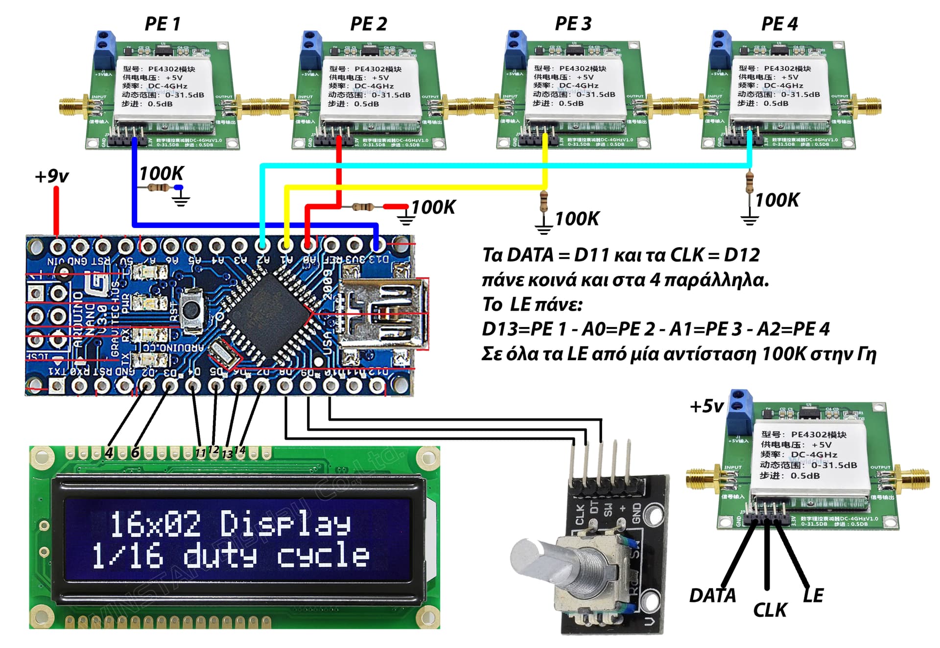
Yes I am a radio amateur and I am building an RF generator. I will try to send you both the program and the design I use. This is supposed to put 4 PE4302 in series, the first 31dbm should be taken (probably) from the first one and the rest should do nothing and then the second one should do the same and so on. Thank you very much for the prompt response! Sincerely
“The TS is a radio amateur, and if he uses the word "attenuator," it means the signal will be attenuated; otherwise, he would have used the word "amplifier." Attenuated by -126 decibels would be nonsense”.
I get that, my point is we are not looking at dbm but simply db. I got my first ticket in ‘63. The dbm is a reference to 1.0 mW. I gave the thread starter links so they could better understand db verse dbm.
I know the difference between decibels and decibels of power. You're right about that. Attenuators operate in decibels (on all the devices I've seen, they need to be converted to power).
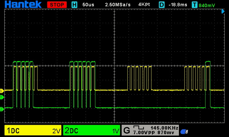
But that's not the point. We're looking for a problem in the code. I showed one: an extra bit in the protocol and delays need to be addressed. It doesn't need a high interface speed, so you can enter a conveniently analyzed speed in the protocol.
Can you please post a copy of your circuit, a picture of a hand drawn circuit in jpg, png?
Hand drawn and photographed is perfectly acceptable.
Please include ALL hardware, power supplies, component names and pin labels.
Cut and paste images do not give clear information.
Can you post some images of your project?
So we can see your component layout.
The pdf of PE4302 you requested
The circuit is simple and as I explained above.
I actually don't know how to program Arduino so I resorted to chatGPT for the code!
If anyone manages to solve the problem, please send it to me in .ino and not in some snippet that is wrong because I won't be able to put it in its place!
Thanks