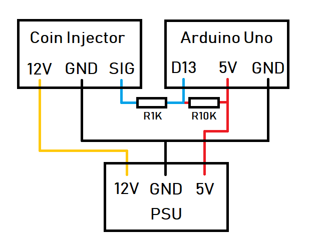
1K resistor between the coin signal and D13 is for safety, while 10K resistor between D13 and 5V is the external pullup, I used external as the internal INPUT_PULLUP still leaves it floating occassionally. Don’t mind the delay for this testing code, as I avoid that for the actual project.
Previously, the coin injector works functionally, but now, after working well for a while, the coin injector pin (D13) would be damaged. I tried using voltage divider too (10K to GND, 20K to coin signal), but it just doesn’t work, using voltage divider (with or without pullups) won’t ever make the Arduino register the coin injector’s inputs.
What’s the solution to prevent damage on Arduino’s D13 using coin injector like this, but by keeping the external pullup? What I have currently are resistors (5.1K, 10K, 20K, 40K, 82K), and also diodes.
Looks as though you have a voltage divider between the 5-V supply and the device output.
The device datasheet just describes the signal as a pulse, but no value. Have to assume it's 12-V DC. It can be set, apparently, to either 20, 50, 100 mS
A voltage divider on the device output needs to be between the SIG and GND.
The datasheet also shows more connections than yours, e.g. a Counter output and Coin signal. Which one are you using?
How have you confirmed that the pin is damaged?
I don't see how it could be.
Supplying 5V to the arduino 5V output can be problematic.
I suspect you have a problem somewhere else.
The outputs of these coin acceptors are open collector / open drain.
This means that the voltage is determined by the user's connections.
Using a pullup resistor to +5V will give a 5V amplitude signal.
There is a selector switch that you can use to select the output transistor being 'normally closed' or 'normally open'.
A second switch selects the pulse width, there is always 100ms between pulses.
You program the coin acceptor to produce the required number of pulses for each coin denomination.
Here are oscilloscope traces showing the types of pulse that can be generated:
The first is a 20 pence coin, output set to 'normally closed' and 'fast'.
The coin mechanism is programmed to produce 4 pulses for a 20p coin (5p base unit).
If the D13 pin is REALLY damaged it looks as if there is a substantial injection of current from somewhere - maybe EMI? You should put a small capacitor from the digi5tal pin to ground.
Your circuit looks OK to me, the input protection will protect you from most transients. If my memory is working D13 is the pin used for the onboard LED which will give you some interesting results. Disconnect the SIG line and run the blink sketch, if the onboard LED is working the port should be OK. Connect the SIG pin to another digital input or you can use one of the analog pins and use the digital read function with it. Happy countint!
I said I used a 10K to GND, 20K to coin signal voltage divider, and the arduino won’t register the input from coin injector, regardless if I used a pull-up or not.
Only the pin 13 is damaged, but I need all the pins in this occassion so I can’t change the pin to other ones. For this post, I don’t use voltage divider, just a pullup to 5V, and also 1K to coin signal is for safety measures. I used the coin signal one.
It’s damaged as it begins constantly inserting credit after it being ran for a while. And yes, already tested D13 with other device (e.g. IR sensor) and the input in D13 is permanently LOW, rather than being HIGH when object is detected and LOW if object is detected as it should be.
I guess using the Blink Example code (as it’s the LED_BUILTIN) and it seems to work for now. Still the question is if my setup damaged the pin or it’s just D13 problem.