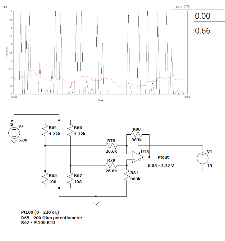
I am trying to measure resistance by reading the voltage change using a Wheatstone bridge and an opamp to amplify the voltage. I have read about the pins "floating", but the voltage I am reading with the arduino is floating from 0 to 5 V when connected to the output of the opamp. When not connected the voltage settles to a constant value, but becomes extremely noisy when connected to absolutely anything.
How would you go about of smoothing this much noise?
The supply to the op amp should not be floating. But if you connect the negative side of the supply to ground then there is a danger that the output could go above 5V if only accidentally. Also you need to be aware that the output swing of a 741 op amp is a little limited.
You still need to be aware of the output voltage swing available. For this op amp datasheet for example the output voltage swing is hidden near the bottom of page 10.
If the Wheatstone bridge is balanced the output of the op amp should ideally be zero volts, but that would be outside its output swing range. You may wish to modify your circuit so the output of the op amp is say 2.5V when the bridge is balanced.
EDIT: You could use the 741 on +15V supply with respect to ground but provide a potential divider to ensure the input to your Arduino cannot go above 5V.
I'm not exactly sure on this part. Do you mean power both the arduino and the 741 using the same power supply except use a voltage divider to lower the voltage for the arduino?
If yes, it is not really possible as I am currently powering the arduino through the USB connection since I need it to collect measurement data.
If not, could you please elaborate further?
I'm not sure about the setup electronically but to answer your question about soothing the noises, I usually add in an average function to take in X amount of data then average it out before printing or before using that data for another equation. The larger X amount, the soother it is.
power the opamp from 0V (GND) and +15V
power the Arduino with 0V (GND) and +5V
Use a 2:1 voltage divider from the output of the opamp to the Arduino analog pin.
Grounds should be shared.
You'd be much better off losing the need for a 15V supply, choose a 5V rail-to-rail opamp. The 741 is ancient and awful - (in 1960 is was amazing, now its a bit embarassing!)
Microchip sell a large range of single/dual/quad 5V opamps of all sorts of performance, many are fully rail-to-rail.
However for a wheatstone bridge like this the natural fit is an instrumentation amp,
not a single opamp.
Perhaps we should avoid the xyproblem and you should state exactly what you are trying to measure?