dlloyd:
If you use this method for relay connections, then there will be no conductive path for EMI to get to the Arduino. The jumper is removed and there is no GND wire to the Arduino. You need to use a separate power supply for the relay board.
Now, all that's left is emissive EMI ... this is where interference can be picked up through floating inputs and other sensitive areas / components on the Arduino circuit board. This emissive EMI is due to contact arcing when the relay contacts break the load.
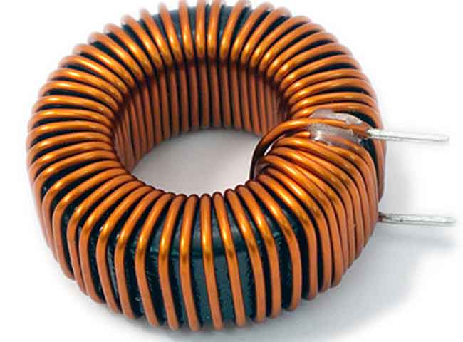
If the problem persists, using a ferrite core on the AC load wire can be a quick and effective solution. In this case, disconnect the load wire that goes from the relay's NC terminal (pin3 in your diagram) and wrap it through the ferrite core with 5 or more turns (the more the better). Re-connect to pin3. Now the arcing will be greatly reduced, the relay will last longer and the emissive EMI problems should go away.
If the problem still persists, try using a longer cable and move the Arduino 2ft or more from the relay board and fluorescent lamp load.
Hi, before I post this question. I have already separate the power like you said. The EMI/spike still there. I think the problem because the load is too high.
Using ferrite corite, what does it mean of 5 turns, is it diameter? Let say, I have load around 8 Ampere. Which ferrite corite should i buy?
dlloyd:
The RC snubber will always conduct current if connected across the relay contacts and the contacts are open (as shown in the link you provided). This current would be enough to cause a fluorescent lamp to flicker or remain dim. A ferrite core solution on the AC load wire will not cause this problem.
yeah, I also realize that.
MarkT:
Signals are either induced (electro-magnetic induction - as used in transformers), capacitively coupled,
or radiated (radio emissions).
Shielding and using balanced signals massively reduces all of them, but a mains transient is approx 1kV
level over a timescale of microseconds, that's perhaps 10^9 volts/second, it takes very little stray capacitance
to couple that into a sensitive part of the circuit - shielding and using groundplanes really helps.
Induction is reduced by avoiding poor layout (big open loops are coils, they couple to any other
nearby open loops - so no open loops, use twisted pair for high current wiring, keep layout tight, keep
transformers and motors well away from your circuit)
RF interference tends to follow lengths of wire and can be much worse if there's an accidental resonance
at the relevant frequency. Ferrite beads/toroids can help block this and reduce such signals getting into
circuits from the wires (actiing as antennas). 100pF to 1nF ceramic caps shorting inputs to ground at
high frequencies also help. Ground planes again highly effective, as are shielded boxes.
Great explanation. So, the electricity come to Arduino by RF (Radio Frequency), right? I will try with ferrite toroid but I wonder which should I buy?