Arduino RGB Led WS2811 not doing anything

Hi there, I bought a RGB Led (WS2811) a while ago, now I'm trying to use it, but it isn't doing anything. I tried seperate libraries (FastLED, NeoPixel).

The LED:
https://www.aliexpress.com/item/5-1000pcs-DC5V-Diffused-round-hat-RGB-LED-with-WS2811-chipset-inside-5mm-F5-8mm-F8/32713415299.html?spm=a2g0s.9042311.0.0.eHw491

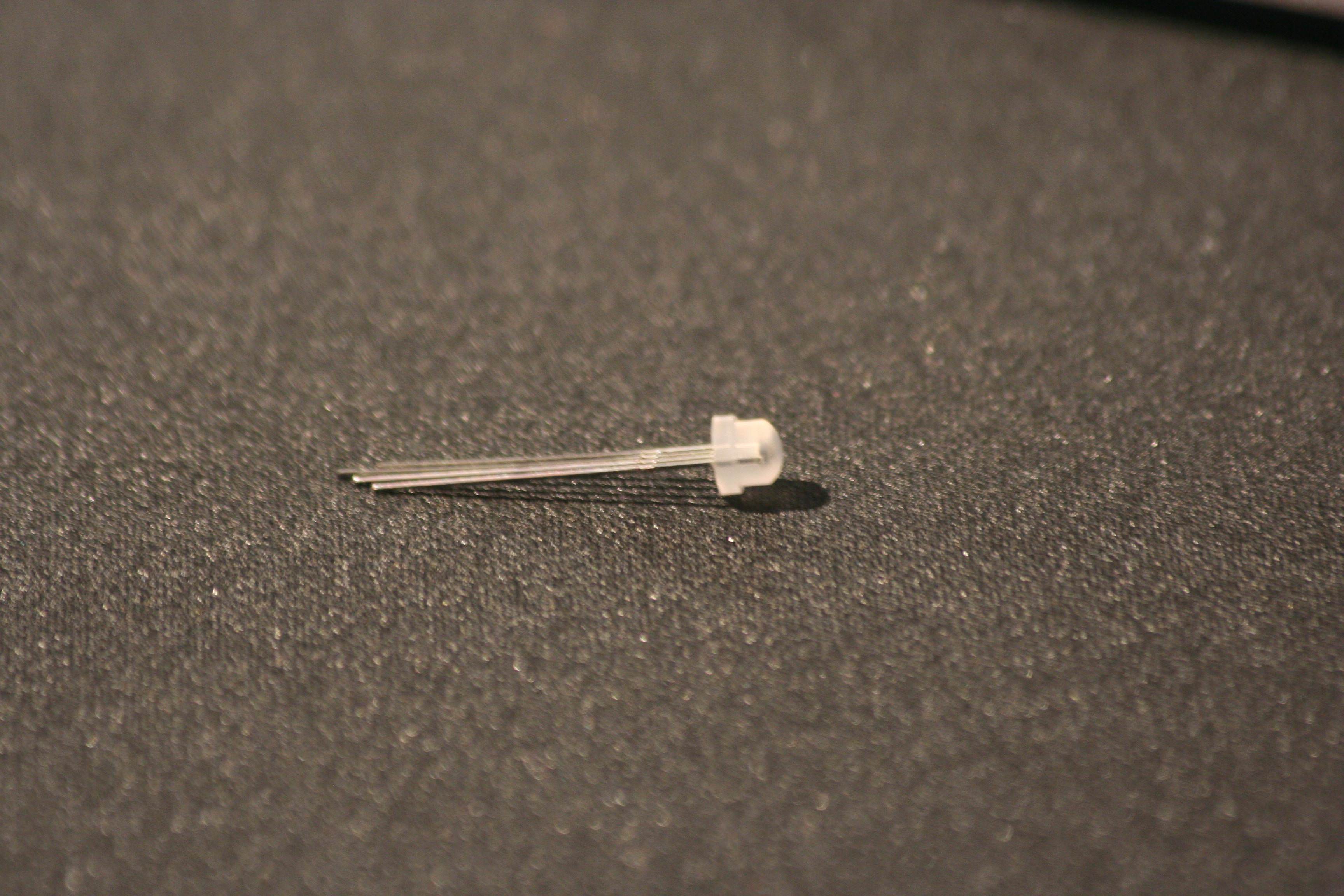
How I connected everything like the seller said:

The code:

#include "FastLED.h"

// How many leds in your strip?
#define NUM_LEDS 1

// For led chips like Neopixels, which have a data line, ground, and power, you just
// need to define DATA_PIN.  For led chipsets that are SPI based (four wires - data, clock,
// ground, and power), like the LPD8806 define both DATA_PIN and CLOCK_PIN
#define DATA_PIN 6
#define CLOCK_PIN 5

// Define the array of leds
CRGB leds[NUM_LEDS];

void setup() { 
      // Uncomment/edit one of the following lines for your leds arrangement.
      // FastLED.addLeds<TM1803, DATA_PIN, RGB>(leds, NUM_LEDS);
      // FastLED.addLeds<TM1804, DATA_PIN, RGB>(leds, NUM_LEDS);
      // FastLED.addLeds<TM1809, DATA_PIN, RGB>(leds, NUM_LEDS);
      // FastLED.addLeds<WS2811, DATA_PIN, RGB>(leds, NUM_LEDS); // use this one doesn't work either.
      // FastLED.addLeds<WS2812, DATA_PIN, RGB>(leds, NUM_LEDS);
      // FastLED.addLeds<WS2812B, DATA_PIN, RGB>(leds, NUM_LEDS);
    FastLED.addLeds<NEOPIXEL, DATA_PIN>(leds, NUM_LEDS);
      // FastLED.addLeds<APA104, DATA_PIN, RGB>(leds, NUM_LEDS);
      // FastLED.addLeds<UCS1903, DATA_PIN, RGB>(leds, NUM_LEDS);
      // FastLED.addLeds<UCS1903B, DATA_PIN, RGB>(leds, NUM_LEDS);
      // FastLED.addLeds<GW6205, DATA_PIN, RGB>(leds, NUM_LEDS);
      // FastLED.addLeds<GW6205_400, DATA_PIN, RGB>(leds, NUM_LEDS);
      
      // FastLED.addLeds<WS2801, RGB>(leds, NUM_LEDS);
      // FastLED.addLeds<SM16716, RGB>(leds, NUM_LEDS);
      // FastLED.addLeds<LPD8806, RGB>(leds, NUM_LEDS);
      // FastLED.addLeds<P9813, RGB>(leds, NUM_LEDS);
      // FastLED.addLeds<APA102, RGB>(leds, NUM_LEDS);
      // FastLED.addLeds<DOTSTAR, RGB>(leds, NUM_LEDS);

      // FastLED.addLeds<WS2801, DATA_PIN, CLOCK_PIN, RGB>(leds, NUM_LEDS);
      // FastLED.addLeds<SM16716, DATA_PIN, CLOCK_PIN, RGB>(leds, NUM_LEDS);
      // FastLED.addLeds<LPD8806, DATA_PIN, CLOCK_PIN, RGB>(leds, NUM_LEDS);
      // FastLED.addLeds<P9813, DATA_PIN, CLOCK_PIN, RGB>(leds, NUM_LEDS);
      // FastLED.addLeds<APA102, DATA_PIN, CLOCK_PIN, RGB>(leds, NUM_LEDS);
      // FastLED.addLeds<DOTSTAR, DATA_PIN, CLOCK_PIN, RGB>(leds, NUM_LEDS);
}

void loop() { 
  // Turn the LED on, then pause
  leds[0] = CRGB::Red;
  FastLED.show();
  delay(500);
  // Now turn the LED off, then pause
  leds[0] = CRGB::Black;
  FastLED.show();
  delay(500);
}

The code uploads good, but there just happens nothing, the led is still off.

I hope anyone could help me.
Switching the + and - cable wont work. Remove the dout cable (data out) wont work either (yes I removed the define clock pin code).

Remy

I searched the whole internet, no resistor needed, I know you don't need the dout, I tried with and without.

Remy

The resistor is needed as it helps protect the chip from damage. It's a a best practice.

you have it wired incorrectly.

DIN and +5v should be next to each other. Based on your code, din is the blue wire and then you have ground and then power, that is nfg.

I can't tell if you have the din in the right place, so it might just be a matter of moving the yellow wire to the spot where the blue pin is.

Connecting the dout pin (which in this case would make it an input) back to the arduino when the pin is registered as an output, could damage the arduino and led. It shouldn't be connected, you should disconnect it.

Your led may already be damaged,

I tried multiple leds, with multiple ways of connecting, I already tried this one (which I said already), with multiple leds, but nothing will work.

Remy

Unless you connect it the right way, you could damage the led.

RemyB:
I tried multiple leds, with multiple ways of connecting, I already tried this one (which I said already), with multiple leds, but nothing will work.

Remy

All your LEDs are dead. Damaged by you without using current-limiting resistors.

You may have tried it, but you still did it wrong, obviously. Otherwise it would be working.

Ws2812 already has current limiting, the resistor is to protect the control chip from onrush currrent

I now use a new led, this should work? (220 ohm resistor)

Still nothing.

Remy

The resistor goes between din and the digital pin. In your picture it looks like it is going between the five volt rail and the Vcc pin.

You need to post the code you are using with that led.

How are you identifying the legs? E.g., how do you know the led isn't flipped. You cannot try it both ways because you may damage the led if you plug it in the wrong way.

Hi,

I see I uploaded the wrong picture, but I have the resistor between port 6 & the data in.

I have 15 same led, so..

Remy

So you may have destroyed that led as well.

Post a picture of the led not installed, and point to which one you think is the DIN pin.

Too fuzzy! We can't tell where the flat on the led is.

Can you post a top down picture of an unmolested led?


Something like this? The best picture I could take in this light.

Remy

Sorry, top down so we can see all the pins before they are bent.


Looks like the pinout, however it says it is for APA106 not ws2812