Hi,
i'm (like most) new into electronics.
i want to make a scoreboard.
front side 2x 0.8 inch anode single digit segment display & 4x 5 inch anode singel digit segment display.
back side 2x 0.8 inch anode single digit segment display & 2x 0.8 inch anode single digit segment display
i have bought myself a starter kit with an arduino uno, and just to start off some 2 and 1 0.8 inch anode segment displays.
played a little on thinkercad and have a working 1 digit 0.8 anode segment display that counts from 9 to 0.
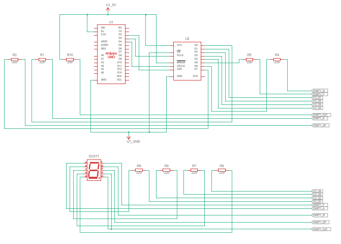
the arduino is connected to a shift register 74HC595 that goes to a ULN2803apg (reason is when i start with the bigger display), both anode com's are connected to the +5v with a 33O ohm resistor.
now here is my question for now;
numbers 9, 8, 6, 5, 4, 3 and 2 are less bright then numbers 7 and 1. why is this and how can i fix it.
many thanks for your guidance.
Post a schematic. It seems like more segments means dimmer segments.
a7
You will get more assistance if you read and follow the guidance in the pinned post in most categories/sub-categories entitled 'How to get the best out of this forum'
Remember, we are not standing beside you.
problem is that i can not give you the scematics, because the ULN2803A does not exist in tinkercad
each output from the shift register goes into an input of the ULN2803A then each output is connected to the segment pins of my display
this is what is have in tinkercad
the resistors between the shift register and display segment needs to be replace with the ULN2803a
not using the resistors on the tinkercad scheme, it's a ULN2803A.
but i have the same problem when using 220 ohm resistors in stead of the ULN2803A
thank you LarryD i did not connected the common from the ULN2803a towards the 5V, now the digit's are nice and bright 
but why do you add resistors between the uln and the segment display when there already resistors inside the uln?
Ah, too bright? If you don't have the series current limiting resistor for each segment, they will be very too bright until they go very too dark…
a7
no normal brightness (and all numbers the same)
Well, he’s wrong, as is far too common with yootoob videos and selfstyled experts.
Try googling “ULN2803 datasheet”; the third or fourth hit should be a link to TI.com, and that datasheet is far more authoritative than your bearded wonder.
Learn to seek out datasheets and read them carefully, it’s one of your keys to the electronics world. Another is a healthy dose of skepticism.
for me a nuby it's not that easy to understand, but what you are suggesting is to put 220 ohm resistors between the segment display pins and the ULN2803a?
and can you please explain why?
As drawn by @LarryD in post#13. If you try to put one resistor on the common pin, then the segment intensity varies with the number of segments lit; one per segment makes the current flow independent.
You will, however, draw more current with the individual resistors. With 220 ohms per LED, your current flow will be around 16 milliamperes per LED. When all segments are lit, you’re drawing 16*8 = 128 ma from the Arduino. That’s pushing the onboard regulator, if your not using USB for power.
so no transistor/output, but one from the 5v towards the common pin?