Arduino table fan with different speed levels - make your own

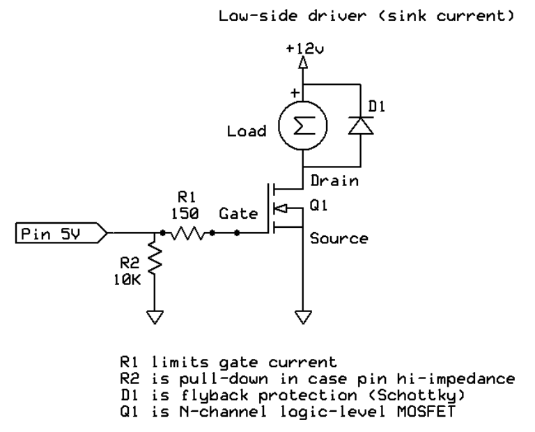
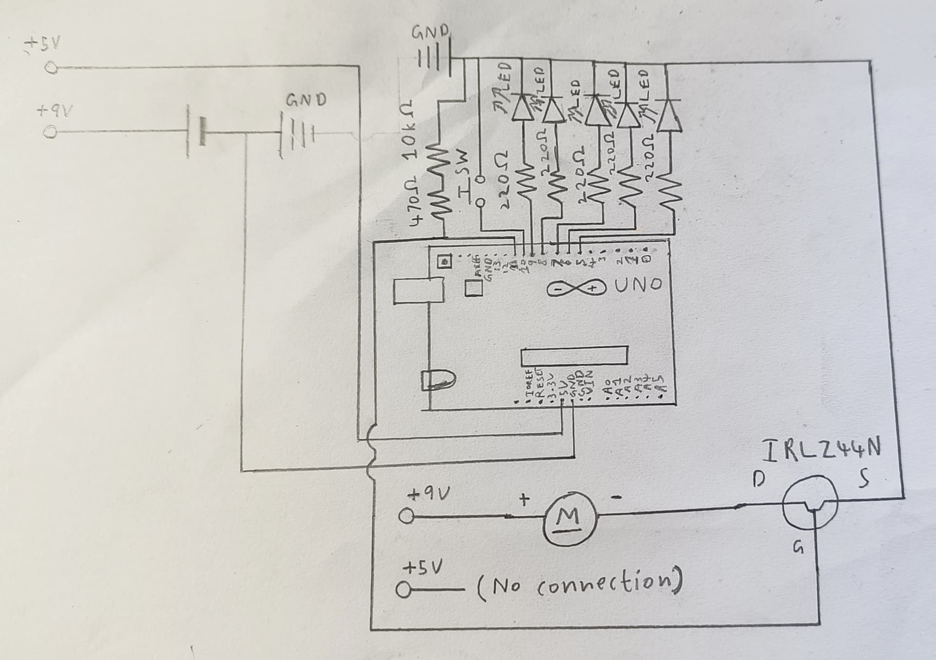
Below, I have provided the code and circuit to make your very own Arduino table fan with different speed levels. You have 5 speed levels, and the speed level is indicated by the number of LEDs that are lit up. If none are lit up, that means the table fan is turned off. When it is turned off, you can press or long-press the button to turn it on. If turned on, you can short-press the button to cycle through the different speed levels or long-press to turn it off. The five LEDs, LED-1, LED-2, LED-3, LED-4, and LED-5, are connected to pins 9, 8, 7, 6, and 5, respectively. The button is connected to pin 10, and for the motor, connect it up with a MOSFET (recommended) for proper control. Additionally, please note that the MOSFET here is an IRLZ44N, which is an N-channel MOSFET that you can use to drive a motor with an Arduino. Connect the MOSFET’s gate pin to pin 11, and ensure the motor has a good power supply. Make sure you properly ground all the components, and also make sure that the motor’s external power supply shares a common ground with the rest of the circuit to work. However, do not do the same with the voltages, as this can cause a short circuit. For button logic, any press shorter than 50 milliseconds is considered noise. A short press will range from 50 milliseconds to 500 milliseconds, and anything above 500 milliseconds is regarded as a long press. Before proceeding, please note that I have only simulated it online as I’m low on parts. If you are planning to build this, test it online first, and be careful not to damage any components when building the contraption IRL.

Happy building!

Code:

const int fan(11);

const int button(10);

const int led1(9);
const int led2(8);
const int led3(7);
const int led4(6);
const int led5(5);

unsigned long prevPressTime;

bool prevButtonState(1);

int thresh1(50);
int thresh2(500);

int fanState(0);

void setup() {
  // put your setup code here, to run once:
  pinMode(fan, OUTPUT);
  pinMode(button, INPUT_PULLUP);

  pinMode(led1, OUTPUT);
  pinMode(led2, OUTPUT);
  pinMode(led3, OUTPUT);
  pinMode(led4, OUTPUT);
  pinMode(led5, OUTPUT);
}

void loop() {
  // put your main code here, to run repeatedly:
  bool currentButtonState(digitalRead(button));

  if ((currentButtonState == 0) && (prevButtonState == 1)) {
    prevPressTime = millis();
  } else if ((currentButtonState == 1) && (prevButtonState == 0)) {
    unsigned long elapsedTime(millis() - prevPressTime);

    if ((elapsedTime >= thresh1) && (elapsedTime < thresh2)) {
      fanState += 1;

      if (fanState > 5) {
        fanState = 1;
      }
    } else if (elapsedTime >= thresh2) {
      if (fanState > 0) {
        fanState = 0;
      } else {
        fanState = 1;
      }
    }
  }

  prevButtonState = currentButtonState;

  int fanVal(map(fanState, 0, 5, 0, 255));

  analogWrite(fan, fanVal);

  if (fanState == 0) {
    digitalWrite(led1, LOW);
    digitalWrite(led2, LOW);
    digitalWrite(led3, LOW);
    digitalWrite(led4, LOW);
    digitalWrite(led5, LOW);
  } else if (fanState == 1) {
    digitalWrite(led1, HIGH);
    digitalWrite(led2, LOW);
    digitalWrite(led3, LOW);
    digitalWrite(led4, LOW);
    digitalWrite(led5, LOW);
  } else if (fanState == 2) {
    digitalWrite(led1, HIGH);
    digitalWrite(led2, HIGH);
    digitalWrite(led3, LOW);
    digitalWrite(led4, LOW);
    digitalWrite(led5, LOW);
  } else if (fanState == 3) {
    digitalWrite(led1, HIGH);
    digitalWrite(led2, HIGH);
    digitalWrite(led3, HIGH);
    digitalWrite(led4, LOW);
    digitalWrite(led5, LOW);
  } else if (fanState == 4) {
    digitalWrite(led1, HIGH);
    digitalWrite(led2, HIGH);
    digitalWrite(led3, HIGH);
    digitalWrite(led4, HIGH);
    digitalWrite(led5, LOW);
  } else if (fanState == 5) {
    digitalWrite(led1, HIGH);
    digitalWrite(led2, HIGH);
    digitalWrite(led3, HIGH);
    digitalWrite(led4, HIGH);
    digitalWrite(led5, HIGH);
  }
}

Circuit:

Hi, @shash_arduino_lover
Sorry but I edited your text to make it easier to read.

You need to fit current limit resistors for the LEDS, you cannot ensure reliable operation if you are overloading the UNO outputs to the LEDs.
Also a series resistor in the gate circuit, say 470R and a 10K resistor between Pin 11 of the UNO and gnd, so that the gate circuit is not floating when you turn your project ON.
What is your MOSFET and is it a logic level device?
Note the back EMF diode on the motor.


A proper schematic would also help.

Thanks.. Tom.... :smiley: :+1: :coffee: :australia:

Thanks. :grinning_face:

Sorry, the MOSFET transistor is an N-channel one.

But what part number, please post a schematic.
Can you please post a copy of your circuit, a picture of a hand drawn circuit in jpg, png?
Hand drawn and photographed is perfectly acceptable.
Please include ALL hardware, power supplies, component names and pin labels.

Tom.... :smiley: :+1: :coffee: :australia:

The part number of the MOSFET is TIP31C.

TIP31C is not a MOSFET, it is an NPN BJT and you are causing damage to your UNO because you have no current limit resistor in the base circuit of the BJT.

Please post some images of your project.

Tom.... :smiley: :+1: :coffee: :australia:

1 Like

I tried it but it does not work.
What could be wrong?

Sorry, the MOSFET is an IRLZ44N.

Please specify the issue that you are facing. This will hep troubleshoot the problem.

First you say TIP31 now you say IRLZ44N.
Which is it?

I’m very sorry, let me just confirm that the N-channel MOSFET is an IRLZ44N, not a TIP31C.

Can you please post a copy of your circuit, a picture of a hand drawn circuit in jpg, png?
Hand drawn and photographed is perfectly acceptable.
Please include ALL hardware, power supplies, component names and pin labels.

Tom.... :smiley: :+1: :coffee: :australia:

Still does not work.

Here is an ASCII circuit schematic.

           +5V
            |
            |
          +-----+
          | UNO |
          +-----+
  Pin 9 ---|>o---/\/\---+---- GND
           LED  220Ω     |
  Pin 8 ---|>o---/\/\---+---- GND
           LED  220Ω     |
  Pin 7 ---|>o---/\/\---+---- GND
           LED  220Ω     |
  Pin 6 ---|>o---/\/\---+---- GND
           LED  220Ω     |
  Pin 5 ---|>o---/\/\---+---- GND
           LED  220Ω     |
           
  Pin10 ---+----[BUTTON]----+---- GND

  Pin11 ---+----/\/\----/\/\----+----+
           | 470Ω     10kΩ        |
           |                       |
           +--------------------+ GATE
                                |
                                |
                           +----+----+
                           |         |
                           | IRLZ44N |
                           |         |
                          DRAIN     SOURCE
                           |         |
                           +----+----+
                                |
                                +----+ DC MOTOR + ---- +9V Battery +
                                     |
                                    GND (common with Arduino)

Please tell me what kind of issue you are facing. This will help us troubleshoot the problem.

Get out pen(cil), paper and ruler.
If you are keen to show your designs you need to be able to provide readable instructions and diagrams.

Tom.... :smiley: :+1: :coffee: :australia:

You have messed me up.
Your schematic does not match your diagram you show in post #1

I built the circuit in post #1 with the TIP31

I don't think you know what you are doing.

My apologies. Below, I have a legitimate hand-drawn circuit schematic for the build with all the details.

My apologies. Please check out my hand-drawn legitimate schematic in post #20.