How many hours?
about 5 hours
How many hours?
about 5 hours
strouhanka:
Could you please help me with this, I don't know which capacitor to use.
Well start off with 100uF in parallel with a 0.1uF ceramic capacitor.
strouhanka:
about 5 hours
What is the current consumption of the system bearing in mind that you are using a multi digit LED display
Given that it will be easier to suggest a suitable battery
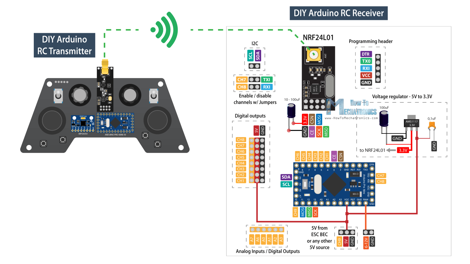
Okay, so I've done some research on capacitors and found out that I should place 10uF capacitor as near to the NRF24L01 as possible.
I also found a project on transmitter and receiver:
And I'm not sure, if I should use ceramical or electrolytic,
You should use both.
Did you not read / understand the link I posted, it explained what this was in that. Ceramic for the high frequencies and electrolytic for the low ones.
The exact placement of capacitors is more of an art than a science, and sometimes you have to use more or move where they are. I would always put a0.1uF ceramic across any electrolytic you use.
What is the current consumption of the system bearing in mind that you are using a multi digit LED display
I know that I should know this, but how can I calculate current consumption?
I tried looking for a Datasheet to the display, but I couldn't find any suitable, on the e-shop where I ordered it, there is only written that the current is 20mAmps
but how can I calculate current consumption
You need to know the forward voltage drop across a segment, and then you need to know what current limiting resistor you have in your circuit.
the forward voltage drop across a segment is 2-to-2.2 volts and the resistor is 220 Ohms
OK so lets say it is 2.1V.
Powering it with 5V leaves 5 - 2.1 = 2.9V to be dropped across a resistor.
Then a 220R resistor with 2.9V across it must be carrying a current according to ohms law of 2.9 / 220 = 13.2mA
So for one display the worst case current is 8 ( 7 segments and the decimal point ) times this = 105.6mA.
If you have a multi digit display then, if it is being multiplexed, this is still the total current value. If they are on all the time, being driven by a latch or shift register you have this current times the number of digits you have.
Thank you very much for all the help and I've got one more question
I would always put a0.1uF ceramic across any electrolytic you use.
Okay, so if I get it right after reading the link once more I should use the electrolytic capacitor for 100uF and 10uF and ceramic for 0.1uF. And when I'm using one 10uF and one 0.1uf with the NRF24L01 which one should be closer to the NRF?
I've got one more question, I want to use MPU6050 gyroscope and accelerometer in receiver, should I put capacitor there as well?
how can I calculate current consumption?
Don't calculate it, measure it
iI don't have anything to measure it with
strouhanka:
iI don't have anything to measure it with
A multimeter, even a cheap one, would be a good investment if there are going to be electronic circuits in your future
strouhanka:
Thank you very much for all the help and I've got one more questionOkay, so if I get it right after reading the link once more I should use the electrolytic capacitor for 100uF and 10uF and ceramic for 0.1uF. And when I'm using one 10uF and one 0.1uf with the NRF24L01 which one should be closer to the NRF?
It doesn’t matter much but have the ceramic capacitor closer to the component you are trying to suppress / protect. This is because the extra track length acts as an inductor and so reduces the high frequencies it can suppress.
Other boards especially if located some distance away might also benefit from extra decoupling.
Okay, so I've 3 last questions.
Can I connect the two GND pins on Arduino together? I know that I already asked this one, but I just wanna make sure, because I couldn't find anything about it on the internet.
Can I leave the unused pins just like that, without any connection to ground or something?
If the PCB looks like this:
The measurements are 120x70 mm. There is Arduino NANO, NRF24L01 module, MPU6050 gyroscope and H-bridge l298n driver module, which will be connected to Arduino through external wires. I added capacitors near to the power source and the NRF, but I'm not sure if I should add some also near MPU6050 and l298n.
Can I connect the two GND pins on Arduino together? I know that I already asked this one
Of course you can, but don't forget to connect at least one of them them to GND of the power supply as well. Equally, using a Nano, if you connect one of them to supply GND you can use the other one as the GND connection for an external sensor, switch or pot for example as the 2 GND pins are connected together on the Nano PCB. Better still, flood fill the PCB and connect the Nano GND pins, the supply GND and any external device GNDs to the flood filled area