Hi, I'm creating a PCB with arduino and would like to know whether I can connect the 2 GND pins on Arduino UNO together.
Thanks for reply in advance
You must do so.
Thank you very much
And when I'm creating a 2 layer PCB, on one side is the ground copper pour and I want the VCC copper pour on the other, should I also connect VIN with 5 and 3.3 V or do it differently?
Do not connect 5V to Vin. Do not connect 3.3V to Vin. How are you powering your board? Do you have a schematic?
I'm using 9V battery to power the Arduino and here is a link to the schematic and PCB layout:
And do not connect 3V3 to 5V either.
The rule is always connect grounds never connect different power rails.
Your link can not work on the Safari browser I have on my iPad.
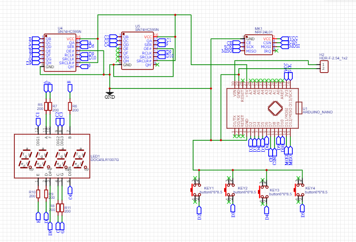
Hi, I'm trying to create two PCBs with Arduino NANO, one as a transmitter, the other as a receiver. I created a schematic and PCB layout for both (EasyEDA(Standard) - A Simple and Powerful Electronic Circuit Design Tool), (EasyEDA(Standard) - A Simple and Powerful Electronic Circuit Design Tool),
I want to use 9V battery to power the Arduino, but I don't know if power supply decoupling is necessary and in case it is, which one to use and how. And I also don't know if I should use some decoupling capacitor or something else with the NRF24L01 module to make the trensmitting more stable.
Thanks for any reply in advance.

strouhanka:
I want to use 9V battery to power the Arduino
Don't! ![]()
Why?
strouhanka:
Why?
By all means use a 9V battery to power the Arduino but not if you mean what I know as a PP3 battery because it has too low a capacity to power the Arduino for any meaningful length of time
Merged topics about the same project
OK, total confusion reigning here! ![]()
When MarkT replied, I believe he was thinking you were referring to mounting a bare ATMega328 because you referred to a PCB.
In fact, you said a "UNO".
But then you illustrate a Nano! ![]()
No, on a UNO or Nano - or most other assembled modules, you do not need to connect both grounds together. There may sometimes be advantages in doing so, but not in the general case.
A Nano makes an excellent "daughterboard" for your own PCB. If you did not want to re-program it or connect to a PC in normal operation, a Pro Mini would be appropriate - and waste less battery power. Because the digital logic is already concentrated on the Nano module, ground or Vcc pour is not very significant at all.
Now, you are multiplexing a 7 segment display. You are using 74HC595s which are not suitable for this purpose (and in general neither is the Nano). You have 220 Ohm resistors in the segment lines, but to multiplex, the current of all the segments must be carried by the driver to one digit pin, which the 74HC595 is not capable of doing, even if it was adequate to properly drive the segments.
At worst, you need to provide transistors to drive the digits. Far better is to use a proper display driver, the MAX7219. Not only can this actually drive the display without segments fading depending on how many are lit per digit, and drive it very brightly if you need to, but it performs all the multiplexing for you so you do not have to write the very precise code to do that while performing your other functions..
But it gets worse!
You propose to connect a 9 V battery to "Vin" and power a NRF24L01 to the 3.3 V pin! ![]()
Certainly, a "PP3" battery will be useless.

As will be the on-board voltage regulator of the Nano when expected to power the display and NRF24L01.
I'm sorry I wrote it false at the beggining, there should also have been NANO.
But it wouldn't harm if I used the GND pour, would it?
I'm not sure, whether I completely understood what you wrote, but I've already tried connecting the Arduino NANO with the 4 digit 7 segment display and two 74HC595s and it worked fine.
I wanted to use 9V alkaline battery. So this wouldn't provide the Arduino with enough power?
So this wouldn't provide the Arduino with enough power?
How long do you need it to run ?
Minutes ?
Hours ?
Days ?
A Lithium PP3 will have a capacity of about 1000mAh if you are very lucky and don't forget about the power wasted by the Arduino linear voltage regulator
Have you tried measuring the current taken by your project with a 9V supply ?
but I don't know if power supply decoupling is necessary
Yes it is. Batteries are a high impedance source so decoupling is required to reduce this.
How long do you need it to run?
I would say hours maximally and I was planning to use the battery boxes with on off switches.
Yes it is. Batteries are a high impedance source so decoupling is required to reduce this.
Could you please help me with this, I don't know which capacitor to use.
If you read a few articles on decoupling, you will see what is recommended.
Google is your friend ![]()
In a nut shell, add one .1uF capacitor as close as and between the power pins and ground pins of each I.C.
A ceramic capacitor is a good choice, also a reservoir low ESR capacitor is recommend 10uF to 100uF on power traces.
How long do you need it to run?
I would say hours maximally
Could you be more ambiguous? How many hours? 2? 10000?