maybe if it was always getting scrambled, but no..
something else, i think..
~q
Here is the current setup after someone else had mentioned that it's not good to stick scope probes into the terminals of something and that it should be put on a breadboard first...
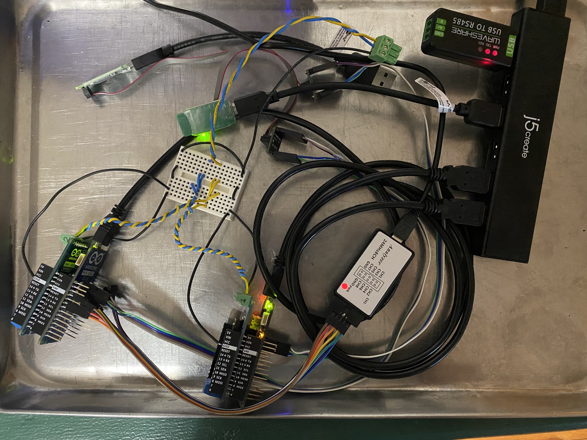
I'll try hooking logic analyzer up to the bus again and see what is there...
lose the breadboard first thing..
and get it out of that metal pan..
got something not so conductive??
maybe old box top..
~q
Alrighty, will do that. (I just put everything in the metal pan because I wanted something to carry it in altogether but didn't think about the conduciveness...) Old box top like cardboard?
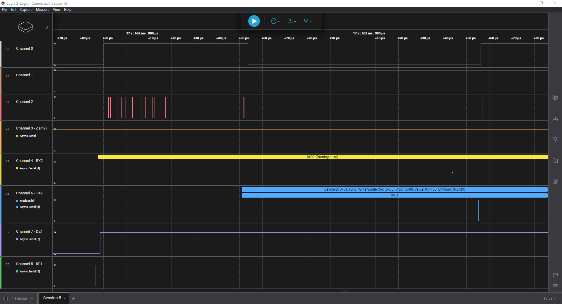
Before I do though, here is a scan with Channels 0 and 2 being the inverting and non-inverting sides plugged into the breadboard...

So, looks like there is a little noise mostly on the beginning and a little on the end?
maybe that's it..
because mostly messing with the first few bytes, end bytes always look good..
~q
yes, that would be better, probably picking up Mars rover now, big ole antenna..
want to add, nice job with the scope.. nice to see the waves..
~q
Ha! That's probably right!
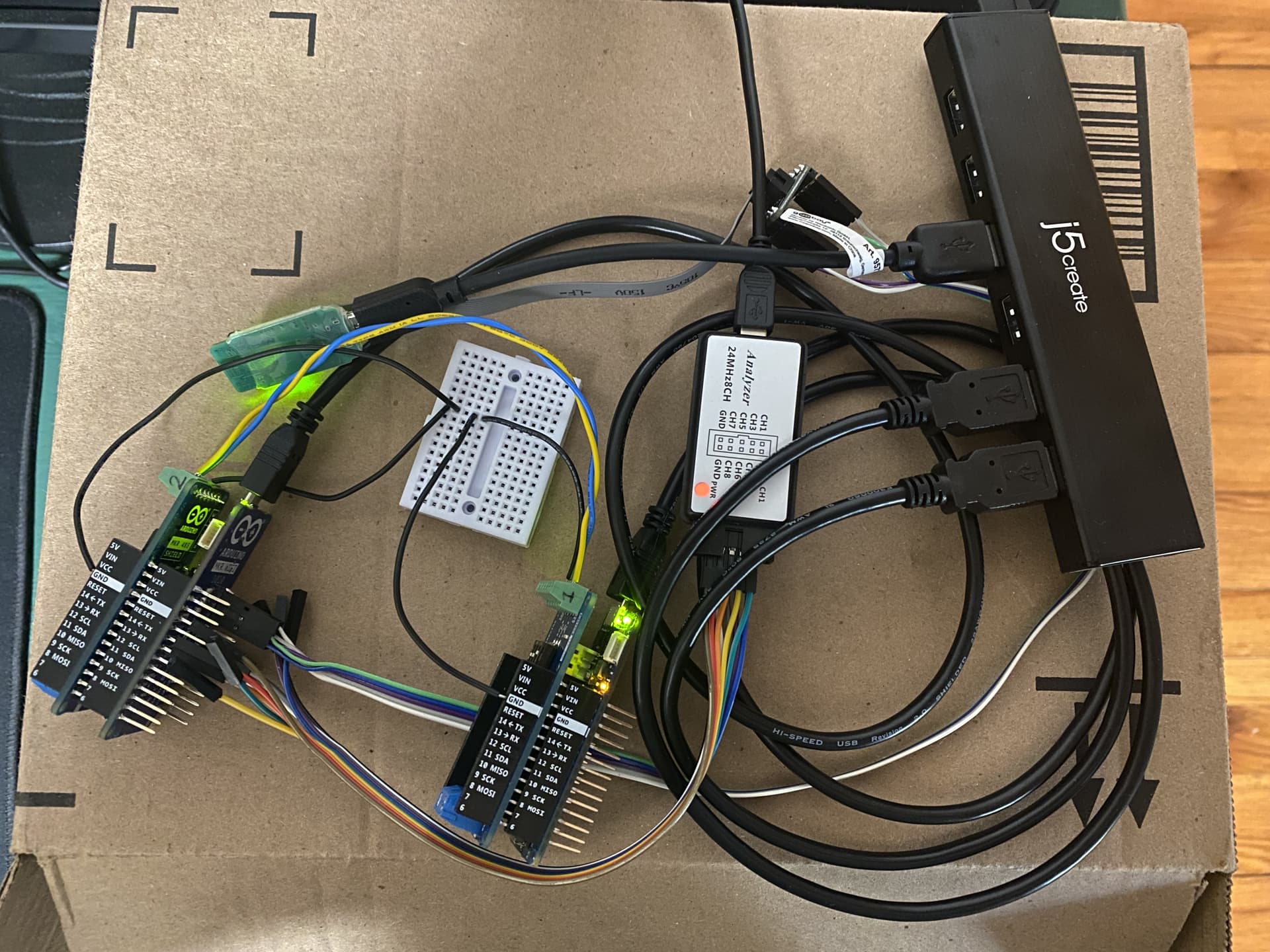
Here is the new setup:
I modified your client to toggle between on and off states, and the message basically always fails now instead of just occasionally failing. This is so strange to me...
#include <ArduinoRS485.h>

const uint32_t TIMEOUT = 500UL;

const byte data1[] = {0x01, 0x05, 0x00, 0x00, 0xFF, 0x00, 0x8C, 0x3A};
const byte data2[] = {0x01, 0x05, 0x00, 0x00, 0x00, 0x00, 0xCD, 0xCA};
const int data_size = sizeof(data1);
byte* data;

byte toggle = 1;

byte buf[80];

void setup() {
  Serial.begin(115200);
  RS485.begin(9600, SERIAL_8E1);
// Enable data reception
  RS485.receive();
}

void loop() {
  if (toggle ^= 1) {
    Serial.println("Sending data1...");
    data = (byte*)data1;
  } else {
    Serial.println("Sending data2...");
    data = (byte*)data2;
  }
  sendTest();
  delay(10000);
}

void sendTest() {
  uint32_t startTime = 0;
  uint8_t  byteCount = 0;
  memset(buf,0,sizeof(buf));
  delay(10);
  RS485.noReceive();
  RS485.beginTransmission();
  RS485.write(data, data_size);
  RS485.endTransmission();
  RS485.receive();
  RS485.flush();
  startTime = millis();
  while (millis() - startTime <= TIMEOUT) {
    if (RS485.available() && byteCount < sizeof(buf)) {
      buf[byteCount++] = RS485.read();
      Serial.print(buf[byteCount - 1],HEX);
      Serial.print(" ");
    }
  }
  Serial.println();
}


Unfortunately can't look at the bus line to see if there's any problems there, HOWEVER, it just doesn't make sense, because these probes are hooked up to the pins on the MKR board itself which means that this is all data that should be received?
So, for sanity...
The TX and RX pins are the communication between the SAMD chip on the Arduino and the MAX chip on the 485 shield. The MAX chip drives the RX pin to the SAMD chip while the SAMD chip drives the TX pin to the MAX chip... So, this verifies that the MAX chip works and is doing its job, but somewhere along the lines, the SAMD chip / Arduino (RS485) library(?) is messing up?
Because, if the TX/RX pins show data correctly, then there really shouldn't be any problems in data transmission part of the system, right?
Of course! Hard to really know much without them...
OH! I can't remember if I've mentioned this before or not, but the LED on the server side still blinks. So basically, I could ignore all these error messages and just blindly send out Modbus messages... could be fun!
¯_(ツ)_/¯
Sorry dinner..
yeah, it's on the client receiving the valid response, so yeah, it's working you just don't get confirmation..
curious, does it make any difference if you move the flush() back to just after the write()??
and just for giggles, comment the noReceive(), receive() in the function to see if we get a perfect double response like we did before..
this may be telling us something..
~q
Oh, yeah, perfect mirror... But when I tried commenting out the receive() and noReceive() out in the libmodbus, nothing changed...? HOWEVER, when I then also added the flush(), no errors showed up and it worked perfectly... HMMMMM!...


Libmodbus code inside the ArduinoModbus library:

. . . . .
I don't think I have even the foggiest where to be looking next if this is the case... That's so weird...
not sure if the double valid response will muck you up or not..
depends if the lib throws out the extra response or is it sitting in some buffer..
this has something to do with switching the recv off and on..
don't have one of these shields, i see switches, what do they do and have you tried experimenting with different settings??
~q
flip the both up and take a pic, so I can see switch configurations and wire connections please..
~q
wires should be middle 2 pins..
switches should be all off on one and 1,3 on for the other..
switch 1,3 are terminating resistors..
switch 2 is half duplex, 2 wires..
~q
So, I just moved the functions around a bit to avoid the double response problem:

And the waveform looks normal and there are no errors. Of course, the problem is I don't know how to artificially send an error... Unless I just create something similar to what you gave me...

The dip switches on the top are A-B termination resistor, half or full duplex, and a Y-B termination resistor. You can download the schematic on the store page and check all this stuff.
sweet, so by moving the recv, noRecv you fixed it..
good job..
~q

The only difference between the setup now and in this picture is I have all the grounds tied together (hence the breadboard).
just terminate the last one, the end of the chain..
switches all off on the first, and 1,3 on at the end..
~q
Yeah, and adding in the flush()... It doesn't seem to work without the flush(), so let's hope that's the fix!
I'll definitely be back with updates later. Thanks again so much for all your help, @qubits-us!!!!! =)
1 Like
the flush is for the write..
it flushes the outgoing buffer..
~q
You're saying that you only need one termination resistor per bus so to say? And that I should have both termination resistors on even if I'm not using A-B?