Greetings my fellow comrades,
This is my first ever post on any sort of forum / stack overflow style thing, so please let me know if I can update anything to be easier to read or understand.
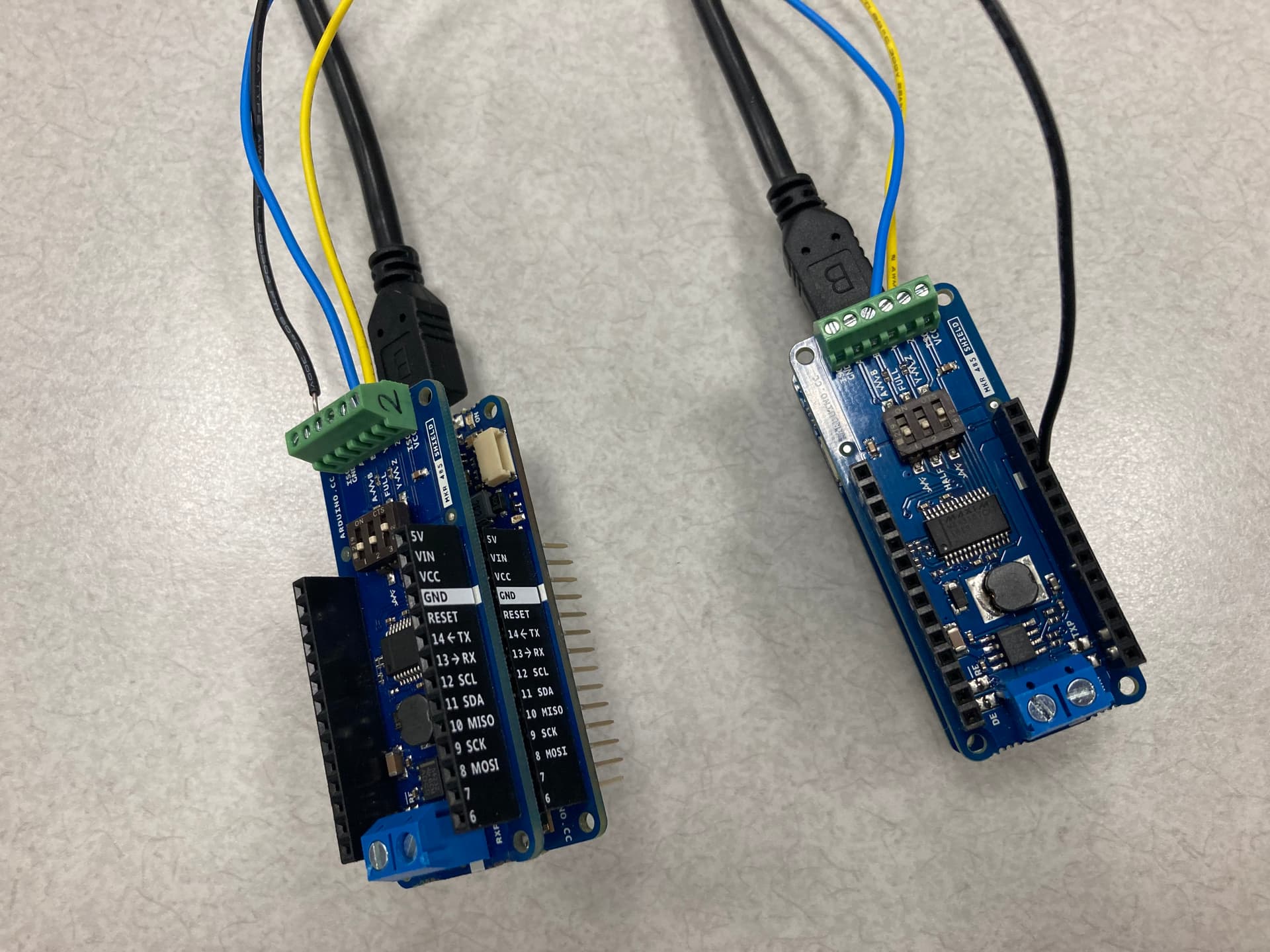
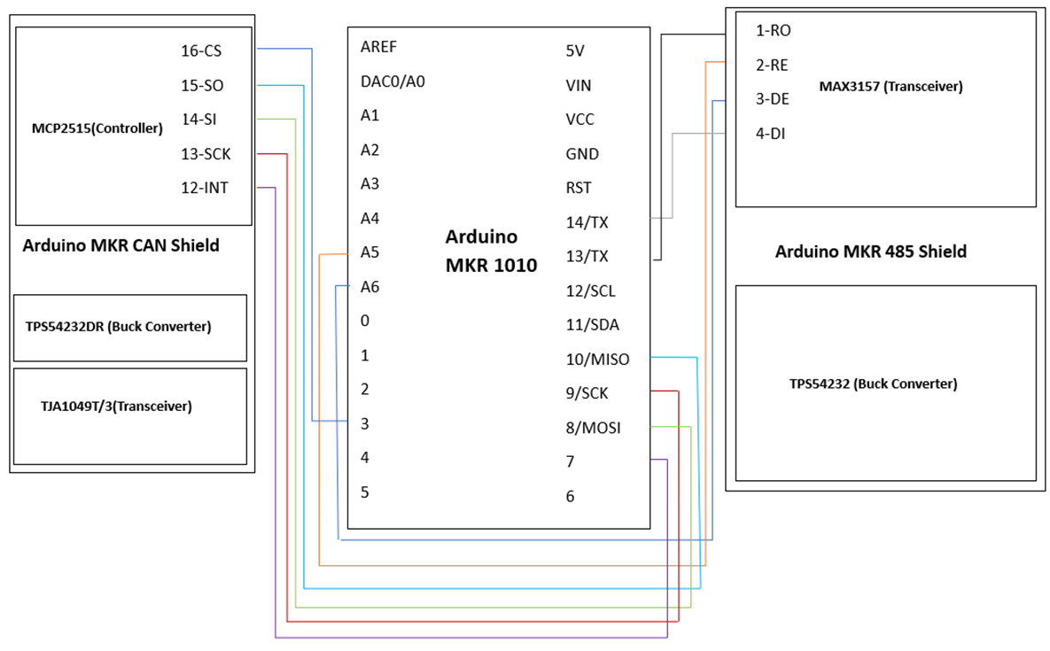
Anyways: Working on a project with an Arduino MKR1010 and MKR CAN and MKR 485 shields to be the controller and communicate with some sensors and such. So far, the Modbus on the MKR 485 shield is providing to be more of a challenge--it's essentially a black box that doesn't work for me.
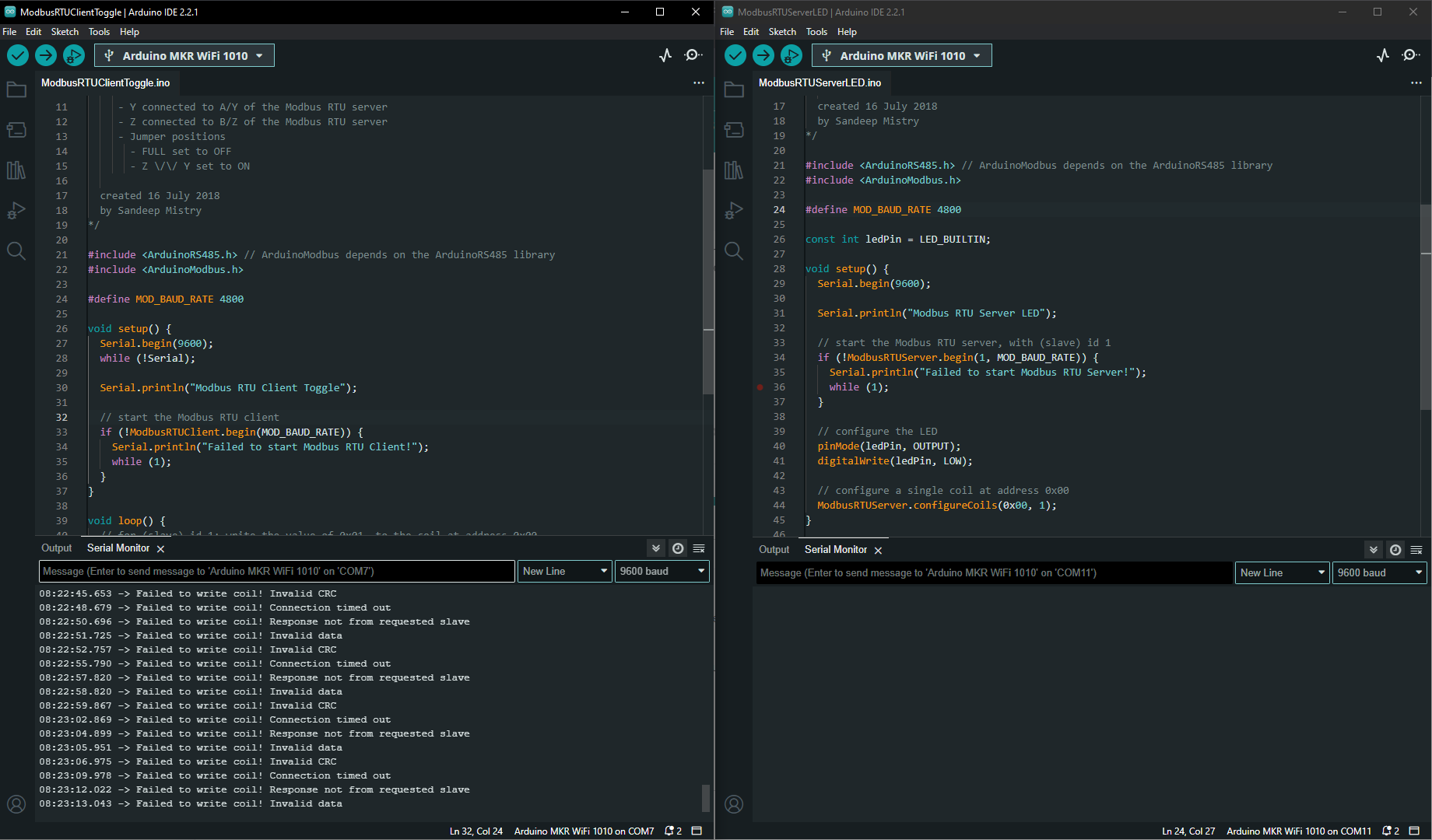
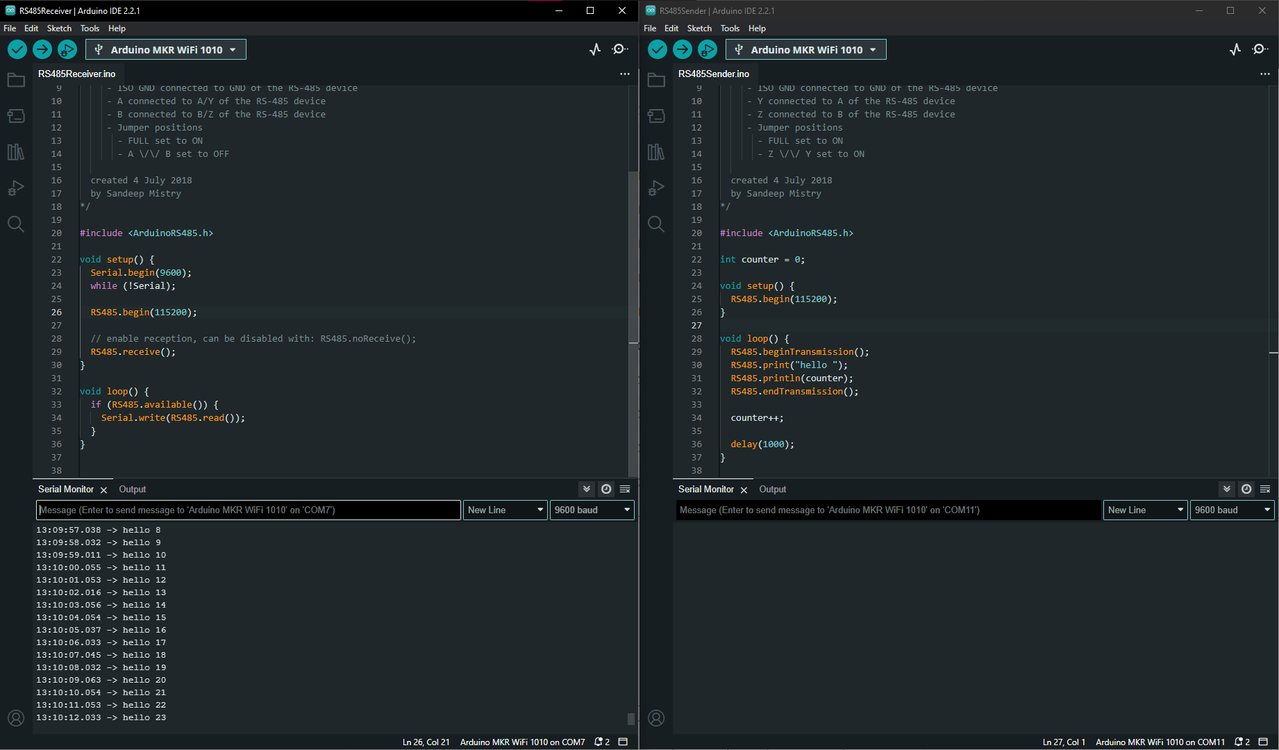
I followed the entire guide on the Getting Started for the Arduino MKR 485 shields. The guide works great for 485 (although, I had to lower the baud rate to 4800 like in this post), but when I then try to load the ArduinoModbus example files (Specifically: Examples → AdruinoModbus → RTU → ModbusRTUClientToggle & ModbusRTUServerLED) included below for convenience:
ModbusRTUServerLED:
/*
Modbus RTU Server LED
This sketch creates a Modbus RTU Server with a simulated coil.
The value of the simulated coil is set on the LED
Circuit:
- MKR board
- MKR 485 shield
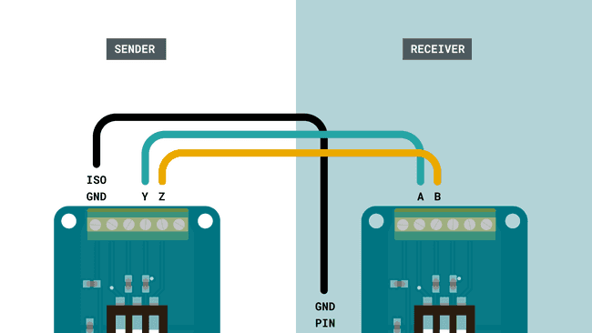
- ISO GND connected to GND of the Modbus RTU server
- Y connected to A/Y of the Modbus RTU client
- Z connected to B/Z of the Modbus RTU client
- Jumper positions
- FULL set to OFF
- Z \/\/ Y set to OFF
created 16 July 2018
by Sandeep Mistry
*/
#include <ArduinoRS485.h> // ArduinoModbus depends on the ArduinoRS485 library
#include <ArduinoModbus.h>
#define MOD_BAUD_RATE 4800
const int ledPin = LED_BUILTIN;
void setup() {
Serial.begin(9600);
Serial.println("Modbus RTU Server LED");
// start the Modbus RTU server, with (slave) id 1
if (!ModbusRTUServer.begin(1, MOD_BAUD_RATE)) {
Serial.println("Failed to start Modbus RTU Server!");
while (1);
}
// configure the LED
pinMode(ledPin, OUTPUT);
digitalWrite(ledPin, LOW);
// configure a single coil at address 0x00
ModbusRTUServer.configureCoils(0x00, 1);
}
void loop() {
// poll for Modbus RTU requests
int packetReceived = ModbusRTUServer.poll();
if(packetReceived) {
// read the current value of the coil
int coilValue = ModbusRTUServer.coilRead(0x00);
if (coilValue) {
// coil value set, turn LED on
digitalWrite(ledPin, HIGH);
} else {
// coil value clear, turn LED off
digitalWrite(ledPin, LOW);
}
}
}
ModbusRTUClientToggle:
/*
  Modbus RTU Client Toggle

  This sketch toggles the coil of a Modbus RTU server connected via RS485
  on and off every second.

  Circuit:
   - MKR board
   - MKR 485 shield
     - ISO GND connected to GND of the Modbus RTU server
     - Y connected to A/Y of the Modbus RTU server
     - Z connected to B/Z of the Modbus RTU server
     - Jumper positions
       - FULL set to OFF
       - Z \/\/ Y set to ON

  created 16 July 2018
  by Sandeep Mistry
*/

#include <ArduinoRS485.h> // ArduinoModbus depends on the ArduinoRS485 library
#include <ArduinoModbus.h>

#define MOD_BAUD_RATE 4800

void setup() {
  Serial.begin(9600);
  while (!Serial);

  Serial.println("Modbus RTU Client Toggle");

  // start the Modbus RTU client
  if (!ModbusRTUClient.begin(MOD_BAUD_RATE)) {
    Serial.println("Failed to start Modbus RTU Client!");
    while (1);
  }
}

void loop() {
  // for (slave) id 1: write the value of 0x01, to the coil at address 0x00
  if (!ModbusRTUClient.coilWrite(1, 0x00, 0x01)) {
    Serial.print("Failed to write coil! ");
    Serial.println(ModbusRTUClient.lastError());
  }

  // wait for 1 second
  delay(1000);

  // for (slave) id 1: write the value of 0x00, to the coil at address 0x00
  if (!ModbusRTUClient.coilWrite(1, 0x00, 0x00)) {
    Serial.print("Failed to write coil! ");
    Serial.println(ModbusRTUClient.lastError());
  }

  // wait for 1 second
  delay(1000);
}
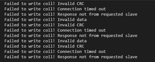
However, I get the following errors:
Failed to write coil! Response not from requested slave
Failed to write coil! Invalid data
Failed to write coil! Invalid CRC
Failed to write coil! Connection timed out
Failed to write coil! Response not from requested slave
Failed to write coil! Invalid data
Failed to write coil! Invalid CRC
Failed to write coil! Connection timed out
Failed to write coil! Response not from requested slave
From my research, I haven't really found anything helpful and honestly just similar posts (like this one without an answer from a year ago).
I'm not really sure where to go from here. I tried switching to half-duplex instead of full-duplex, but that didn't really help the Modbus. I have been poking a lot into the ArduinoModbus library GitHub and the issues and PRs etc. They just give me something else to look into without much luck on actual answers.
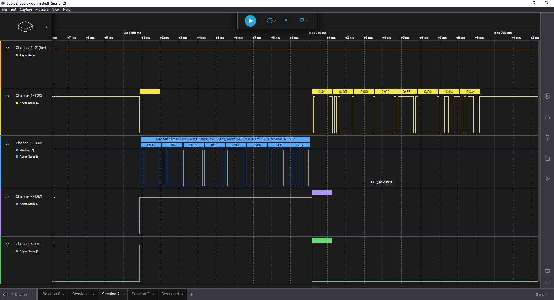
Any answers or tips on where to look or how to debug would be much appreciated! (I have soldered on header pins and been trying to us a J-Link to debug as well as a cheaper logic analyzer (with Saleae Logic software) and an oscilloscope to dig deeper, but maybe I'm in too much over my head?)