Hi, Im a little confused with the pins on Arduino Pro Mini. I found there are two Vcc and 2 GND pins on the board. At which where the input voltage and GND to connect. And to which GND and Vcc sensors or devices attached with the board to connect.
Also little more clarification requesting. Its regarding voltage limit or maximum/minimum voltage required for the Pro Mini (Or Nano) to work well. Something like is there is Good voltage range for the board to work very well.
Also if I have a non regulated supply voltage of around 12v (Little higher sometimes), is that possible to directly connect to Vcc? Or do I need to drop the voltage to 5v using some regulator??
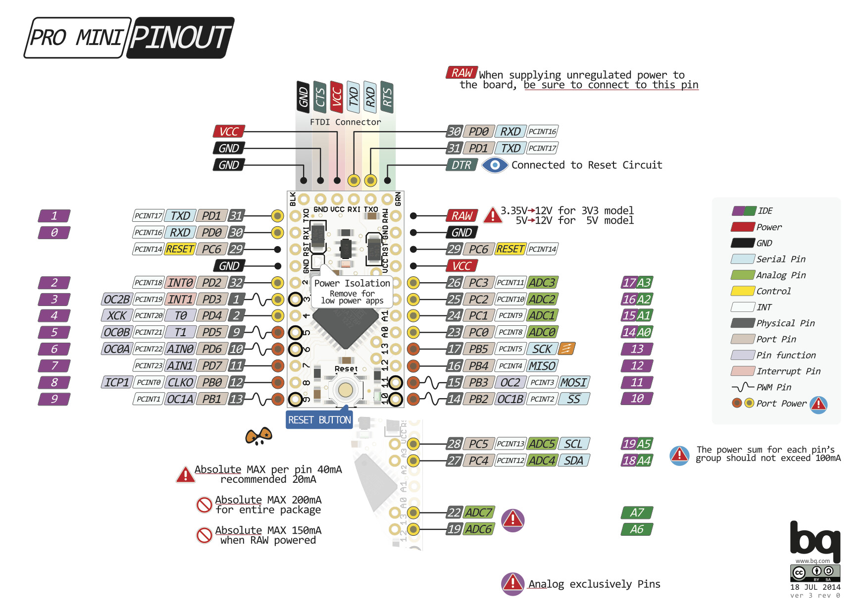
Pro Mini has 4 GND pins, not 2. The ones on either side are simply placed for convenience, their function is the same. Both VCC pins are also having the same function but the one on the top side of the board is placed so that it could be powered using the FTDI cable.
Pro Mini needs a regulated 3.3V or 5V supply (depending on the model) on the VCC pin. If you're supplying unregulated power to the board, be sure to connect to the "RAW" pin and not to VCC. RAW pin can accept voltage up to 12VDC.
Noobian:
Pro Mini has 4 GND pins, not 2. The ones on either side are simply placed for convenience, their function is the same. Both VCC pins are also having the same function but the one on the top side of the board is placed so that it could be powered using the FTDI cable.
Pro Mini needs a regulated 3.3V or 5V supply (depending on the model) on the VCC pin. If you're supplying unregulated power to the board, be sure to connect to the "RAW" pin and not to VCC. RAW pin can accept voltage up to 12VDC.
Decent branded phone-charger supply is the way to go I think. Anything cheap and unbranded connected
to 240V is to be treated as live in my book. And beware cheap and branded (could be fake)...