As you can see, its super basic code, but my multimeter is reading 0.7mA output when the pin is on, with both boards. the datasheet says it should be outputting 40.00mA per I/O pin.
I think it may be an issue with my code, but I think I could also be something else I'm missing as I am new to this.
Your topic was MOVED to its current forum category which is more appropriate than the original as it has nothing to do with Installation and Troubleshooting of the IDE
What are you using as the load on the pins when you measure the current ?
What's the load on the pin? Just because a pin is able to give pinAmps does not mean the pin will output max pinAmps all the time. The current drawn is dependent upon the load requirements. It comes back to
Double check. Chances are good you are actually measuring 0.07A or 70mA. The data sheet doesn't say "it should be outputting 40.00mA". It says 40mA is the maximum that you can draw without damaging the pin. So you are either measuring 70mA, or a damaged pin measuring 0.7mA.
The sensible place to put the probe would have been in series with the line to the relay board, which would tell you the actual current into the relay board. Instead you short circuited the pin.
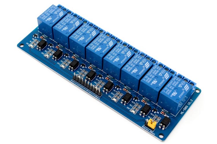
If you are powering a bare relay, don't. You need an interface circuit, that is why people use modular relay boards.
If you look at some of the diagrams on there, it shows all the pins and what they do. The ones I am connected to are the IN1 (relay control 1), VCC and ground. The 24v side of the setup is connected to a pump controller and is working and connected properly so that isn't the issue.
The multimeter is set to mA so I'm certain of the result.
If the relay is has opto-isolation circuitry, then there should be no problem driving the relay. If you are trying to directly drive a relay coil. You'll be needing to have a spate of on hand replacement MCU's.
So we don't play 1000000's of questions and you don't feed us the deets in little pieces. Just fully explain the project.
Post the schematic and images of the project all wired up.
How is the relay module configured to run? Is the relay module powered by the MCU? Just post a schematic and pics, please.
The output on the relay (24v side) will read 24v if the code is on or off regardless. The relay is connected to a pump controller. I am connected to a logic I/O port which responds to our non-Arduino interface, have a look at page 5 for the logic I/O port.
Dumb question i know, but how can i measure it in series, i thought measuring across the connectors would be fine?
Break the circuit at some point and connect the multimeter across the gap in the circuit
Make sure that the meter is on a current range and that you are using the correct sockets on the meter. Some meters have one common socket and separate sockets for current and other measurements
Measuring across the connectors puts a dead short on the pin, because that is what a current meter looks like. It is basic electricity theory, measure across the load for voltage, measure in line with the load for current.
So you might have damaged the pin and you will have to try another.
See the bit where it says prolonged use at that level will cause damage. Notice this is not the maximum the pin can supply, but the maximum it should supply.
In fact depending on the load the current can be almost double this absolute maximum. Which kills the pin a lot quicker.
It is normal to consider 20mA as the rated output, you can push this up to 30mA with some reduction in voltage but never run it any harder.
It shows the maximum operating voltage as 6.0V but as the notice says it might not work at this voltage. We had a user recently that mistook that figure as the maximum they could apply and still have it working. He was wrong.
This is a simplification as this is free software and doesn't have all the parts i use. Resistor representing the load on the circuit and relay showing how one of the modules would be connected. Arduino wont allow me to upload more than one photo at a time as this is a new account
I understand these are maximums and running them at those values will cause inevitable damage, but the load required as shown in the relay datasheet is 5mA which is far below any damaging value. I have since tried new pins and measured in series for the current and there is no change.
Is it safe to assume this is an electrical fault and not a code fault?
How does the power get from the Uno through the breadboard to the relay coil?
From the pic the red line from the relay goes to the breadboard power rail but nothing is connected to the power rail.
Yes there is a red line from the Uno to the breadboard. But there is no connection from the + side where the Uno connects to the other side of the breadboard.
As a note the Uno is NOT a good power source for the relay coils. Especially 8 relay coils. The relay module should use an external power supply instead of sucking power from the Uno.
My colleague, a chartered electrician, has seen the setup and has verified me it is sound. He has measured the current, in series, on the Ardunio side of the relay, and has shown it is not drawing enough current from any of the digital pins.