Ok, so essentially this is using an Arduino to listen to the I2C bus. Curious why he used a 5V board and replaced the 5V regulator rather than using 3V3 board.
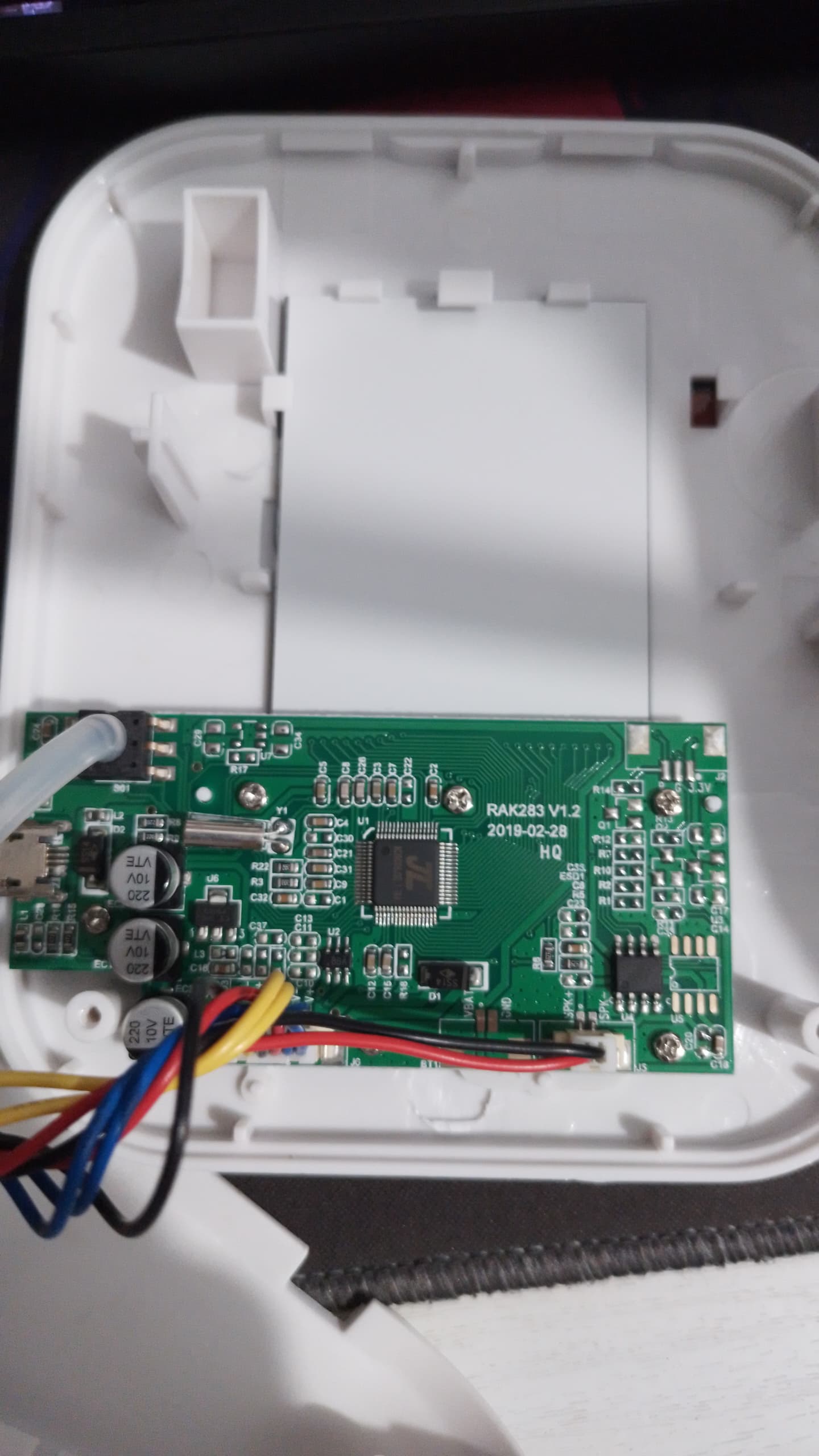
Anyway, when zoomed in, the image is too blurry to read the detail on the chips. The chip in the centre of the 3rd image is the MCU. No idea what the one at the bottom right is. Could be an audio output amp since it is located next to the speaker connections, or it could be an EEPROM. Hard to tell where that track from speaker+ runs exactly. There are 3 tracks that run into vias and might run across to the MCU on the other side of the board.
If you found the datasheet for the MCU, you should be able to look up which pins are the I2C pins and then follow the tracks to find a suitable connection points.
BTW, just because it worked in that video don't assume that it will just work the same on this unit. Assuming you can find the I2C bus and listen to it with the Arduino I2C, there is no guarantee that the format of the transmitted data will be the same. Some additional work may be needed to properly decode the data.
I moved your topic to an appropriate forum category @kenken0713 .
In the future, please take some time to pick the forum category that best suits the subject of your topic. There is an "About the _____ category" topic at the top of each category that explains its purpose.
the one in the third image at the bottom right corner states H10_002_V1, which I could not find any documents for either. And the MCU is AC19CK8J30.I-1A4
But with that said, I noticed there are
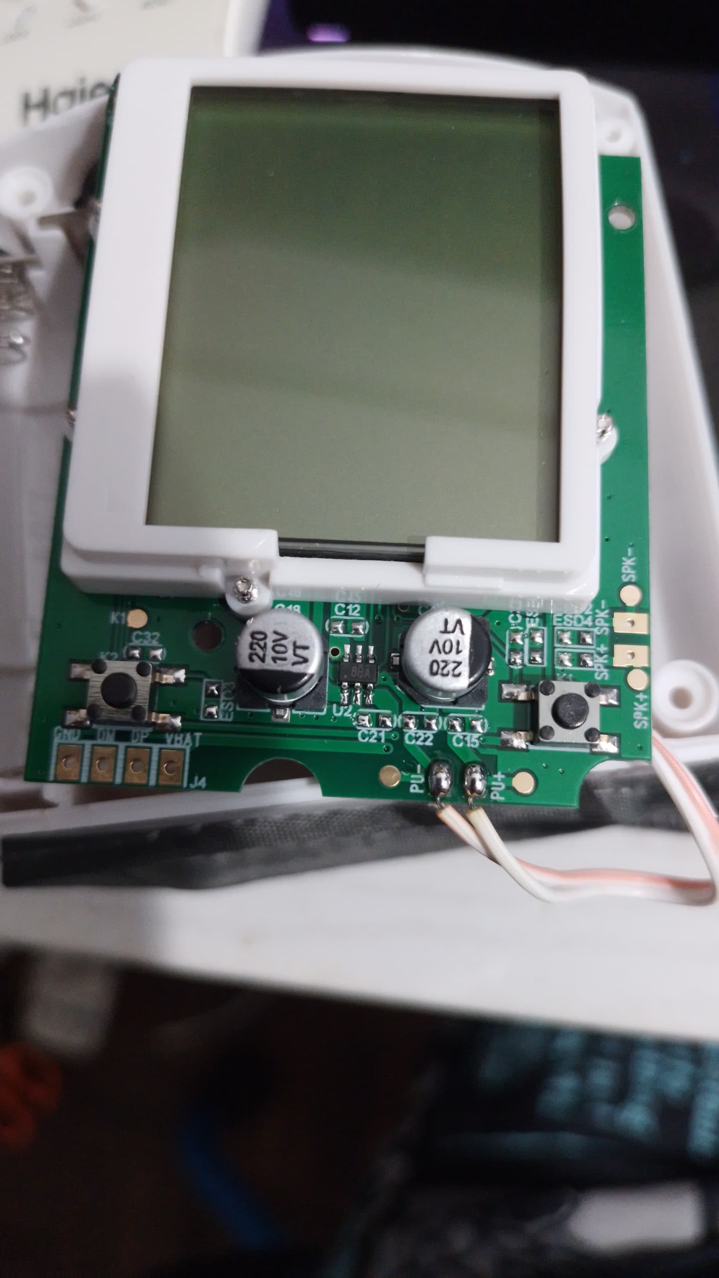
4 pins at the bottom of the first image which are Ground, DM, DP, and VBAT, which seems to be possible to be used via serial, though I still need the arduino to initiate the reading instead of pressing the button on the blood pressure itself, which I have no figure out yet
What is the voltage across the open switch contacts? Is either contact also connected to the device ground? Do the contacts stay connected when the switch is released or does it need to be pressed again to turn off?
Its not just a question of programming skills (which by all means feel free to develop yourself) but of understanding the device and the data format which we know next to nothing about and you are guessing at on the basis of another similar project.
The numbers on the parts you provided are not actual part numbers which doesn't help much unfortunately. That 8-pin chip might be a flash memory but we don't know for sure and can't determine its pinout without a data sheet. We don't know whether it is connected to the MCU via I2C or SPI. It is easy enough to eliminate VCC and GND which leaves 6 pins. It is possible to probe those given the appropriate tools. If there is an I2C or SPI bus, then one of them will have clock pulses and one or two of the remaining 5 should have data pulses on it. If its connected via SPI then your program that reads I2C will need to be re-written anyway to read the SPI port instead. At this stage it is all very much of guessing game still.
BTW, DM and DP will refer to USB data connections not serial so if you are trying to read this as serial then I am not surprised you are getting gibberish. Its more likely that this interface is used at manufacturing time for programming and testing the device.
I will try to guess and solder on that 8pin for now then, for the usb data connection, is there no other way or am I going for the guessing game again too?
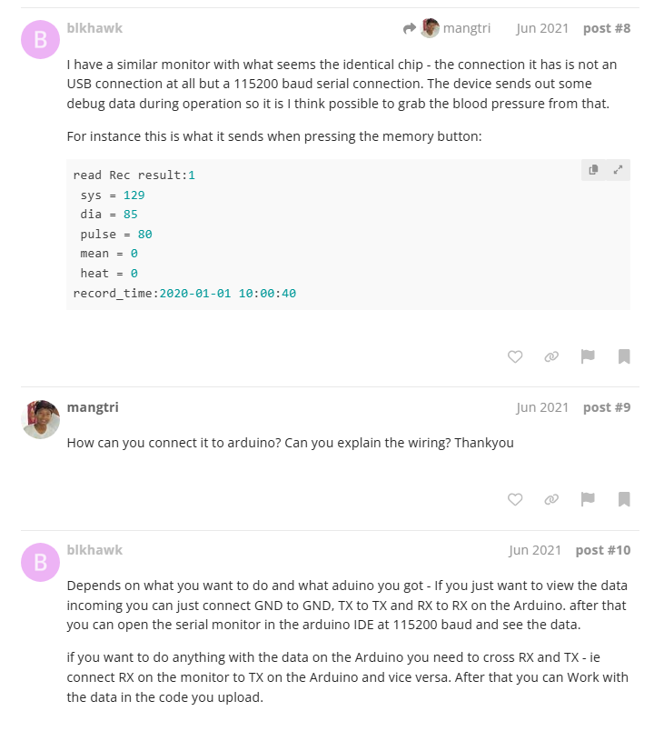
Did you try and do what the last post was telling you to do?
There were two suggestions here. The first one was just to view the data on the serial monitor. This will show you if you have your wiring correct and if it is functioning like it should. If this will not work then it could be you don't have the same device, or your device is not working.
Volt meters don't cut it for these sort of problems especially while trying to look for occasional short pulses. You really need to use an oscilloscope with a good choice of trigger options to track this sort of problem.
last post as in the one in the image? That is the thing I'm not sure what is the code behind it that does that, and as for now, I'm leaving the trigger part aside first, its fine if I have to manually pressed on it, the main problem is that I cant see the results on the serial monitor in the ide