Hi,
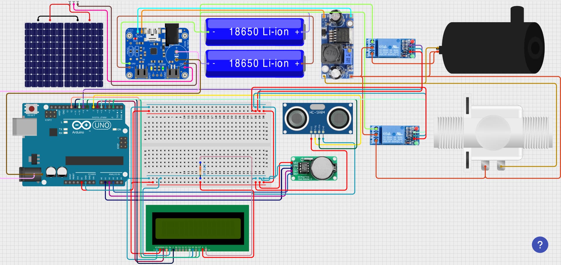
For my project I am making an solar panel powered sprinkler system, as a small prototype. I have two 9v 220mA solar panels connected in parallel to a solar power management board which lowers the voltage to 5V which then charges the batteries ( 2x 18650 cells in parallel ). Which then powers the Arduino, and other components. I am using a real time clock, as a timer for my sprinklers, an ultrasonic sensor which is in the water tank to trigger when water levels go below a certain point. A DC - DC Converter which boosts voltage from 5V TO 12V for the solenoid valve and the water pump for short period of times. When its time for watering the water pump will pump water out of the tank, via a relay. When the water level goes below, then the ultrasonic sensor will trigger, and via a second relay, the solenoid valve will open and pump water from a "dam". I also have an LCD Screen which will display the current time and when is the next watering time. It will also provide with the voltage in the 18650 cells, and also I have a switch to manually turn on and off the project. I just need help with if my circuit diagram is correct, and if it would work, and how would I make a voltage divider circuit for measuring voltage of the 18650 cells. Your assistance would be much helpful for my school project.
That's always a danger with Lithium rechargeable batteries, if they are not handled correctly, and your charge controller can't handle more than one correctly.
That depends on many things. You need to do the maths. If one 18650 cell is not enough, you can get larger batteries. I have used 21700 li-ion batteries in projects. They have 4,000 mAh capacity (tested).
Can you post a schematic? They are easier to read and spot errors in.
I would recommend:
using a Nano V3 instead of Uno, so you can plug it into a (larger) breadboard
Getting an i2c backpack for the LCD to reduce pins required and make wiring simpler.
Getting a waterproof sensor. HC-SR04 will soon rot inside a tank, even though it isn't submerged.
Use MOSFETs instead of relays to save battery power.
Simplify your circuit by reducing the number of different voltages needed by the components. Currently you have 9V, 12V and 5V. Converters are by no means 100% efficient, and every time you convert one voltage to another, you waste some of the power.
In similar projects, I have used 12V panels, 12V SLA batteries, 12V pumps and valves and relied on the Arduino's built-in regulator or an external regulator to make 5V or 3.3V, and minimised the current needed at 5V/3.3V.
In order to have Lithium batteries in parallel, you need a proper BMS and proper charging circuits. For now get a good lawyer, a big fire extinguisher and much insurance (if you can)
HINT you need a 'balance' charger.
I'm gonna push back on batteries in parallel. I have three commercial 2P 18650 charger/boost modules from the Far East, and they seem to work fine. And I suspect many power banks are built the same way.
But there are rules. First, the cells need to be the same voltage when first connected together. Second, thereafter they must never be disconnected. And that means they must be unprotected cells (protection elsewhere in the circuit).
For this purpose (outdoors), it should be ok.
But I don't see any protection on your charger module.
Edit: Is that actually the charger module you will be using? You appear to have the panel wired in incorrectly, and up by the input connector it says "6VDC max".
I think all solar panels at least from reputable dealers have the diodes. That fact will be in the spec.
The old design criteria of panels in parallel to minimize shade issues at the expense of higher losses due to higher current is obsolete. Today we match the panels voltage to the MPPT input voltage. For instance I had 6 190 watt panels. I connected 3 in series with a parallel string of 3S. They were 19V panels so 3 x 19 is 57 volts and the MPPT I matched could handle 75 I think. By doing it that way the current in the wires from panels to MPPT was 2 x 10A. Had I wired all in parallel I would have 60A with huge losses if the same sized wire was used or more $ for a much bigger wire.
NOTE: All power numbers are approximations cuz I am 83 and don't remember the exact numbers.
Sorry, I was thinking real solar panels, 2ft x 5ft. He is just using toy panels. Yes, NO diodes and also probably nowher near the power they say. Count on 50 - 67% of stated.