What via size do you recommend for 10mil (0,25mm) signal traces? 0,6/0,3mm should be enough, right?
I like your image in post 21.
Don’t go less than 6-8 mil for holes (my rule).
Often, a hole can be 1/2 the pad diameter.
Example: 6mil trace, 12mil via, 6mil hole.
Some PCB programs use a percentage.
65% of via diameter.
The smallest via size I’ve used is 20mm 20mil, hole is 10mil, on a 10mil trace.
Traces are kept 10mil or larger.

I like your image in post 21.
Thanks, I've used the AN2519 for the "inspiration".
The smallest via size I’ve used is 20mm, hole is 10mil, on a 10mil trace.
I think you meant 20mil. ![]()
Thanks for the rule of thumb.
Yes ![]()
This is exactly the company, where I'd like to order my prototype. At least when the ATMEGA328P-AU marked as Basic Part will not cost a fortune...should I expect it in the near future?
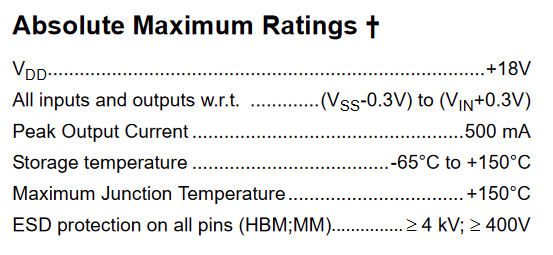
Another thing. When programming the unpowered board through the ISP header, VCC is supplied by the programmer and the MCP1703 voltage regulator output pin (in the current layout) goes up to 5V also. The datasheet states that any output pin should not go above (Vin+0.3V) which is 0.3V in this case. How could this be resolved without losing any of the output voltage (on a diode for example) from the regulator in normal operation?
Another thing. When programming the unpowered board through the ISP header, VCC is supplied by the programmer and the MCP1703 voltage regulator output pin (in the current layout) goes up to 5V also. The datasheet states that any output pin should not go above (Vin+0.3V) which is 0.3V in this case. How could this be resolved without losing any of the output voltage (on a diode for example) from the regulator in normal operation?
Or I could simply leave the ISP header VCC pin unconnected, and the board will be only programmable if the voltage regulator is powered from the input side.
This topic was automatically closed 180 days after the last reply. New replies are no longer allowed.