Correct. You can use D0/D1 as Serial, perhaps to a local device as well as teh USB, or you can use them a digital IO, but not both at the same time. The 1k resistors allow digital or "local serial" use even though the pins are also connected to the USB/Serial Converter.
there are legs on ATmega2560 that are not connected to anything
I think the Arduino team just ran out of room around the edge of the MEGA board. There is no particular technical reason not to use those pins, and other 2560-based boards have done so.
(In slightly newer designs, it's common to wire the SPI/ISP connector, I2C pins, on-board extras, and USB Serial pins from microcontroller pins that are NOT connected to board-edge pins. For instance the Arduino Zero. If you're not sticking to the MEGA board layout, anything goes (although you'll have to change the files in hardware/variants.))
Some of your comment have attracted flags to the moderators for being rude. I have deleted some of your replies where I have agreed with the flags. I realise there is probably a language issue here as English is probably not your first language, but being polite is not language specific. Please moderate your language in future. More rude comments are likely to result in a ban from posting.
Everyone else,
In deleting rude comments I have also deleted replies to them, otherwise the replies would not make sense if I left them in. My apologies to you if I deleted your reply.
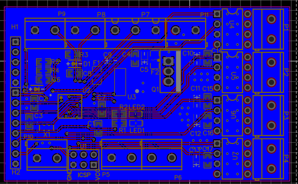
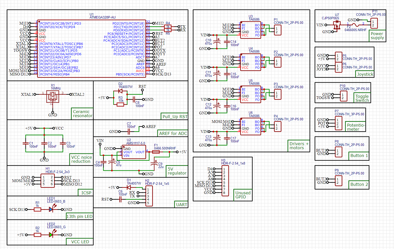
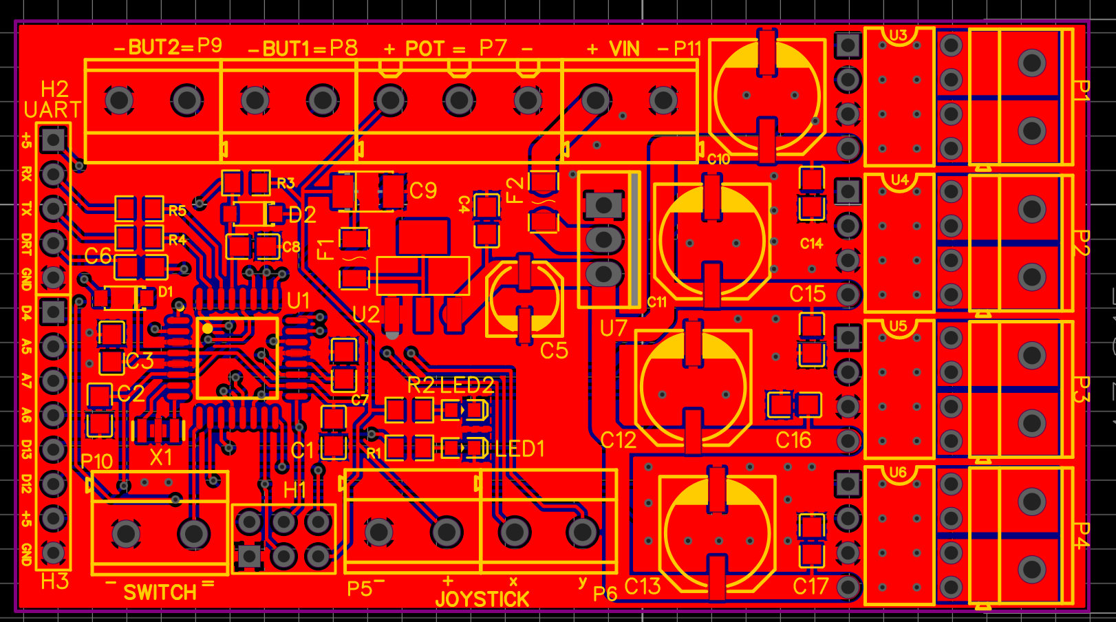
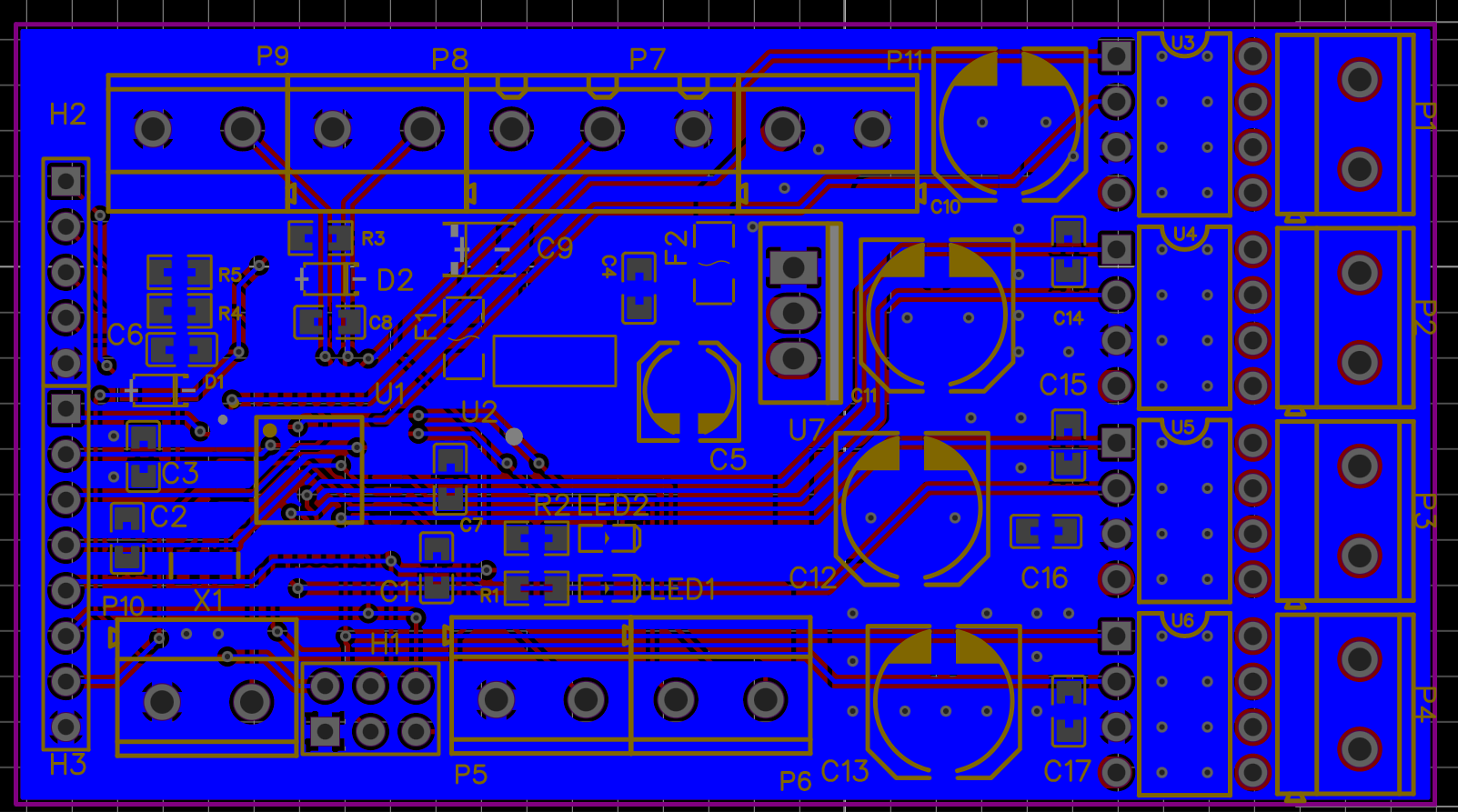
So this is my final version:
1)Added input capasitors for stabilizer ams1117(two bulk caps one before, one after) Did that according to ams1117 datasheet and Arduino Uno scheme.
2)Changed footprints for fuses, I am gonna buy them by myself, so changed footprints on 1206.
3)Added reverse voltage polarity protection from this video. I hope it works.
4)I double checked from some people about TA6586 driver. It seems that it finaly can handle my my motors. I want to make a bet and try to use them instead of drv for now.
5)Switched places for some logic I/Os
6)Lead out unused GPIO(including MISO and SCK). If I am right I can use MISO, MOSI, SCK if i want, since using MISO for ISCP and using MISO as D12 GPIO are not parallel operations, so that should be fine I guess. It is not the same as TX and RX.
7)Added some randoms vias, not sure if they will do the trick with heat dissipation, but I hope at least they will not make it worse.
So yeah, I am going to order the board in about 6 hours. If I made any crucial and life changing mistakes, you are very pleased to give a comment! Thanks everyone for help! I think that it is very important experience for me, I learned a lot, but still not enough. So yeah, I am good to go towards more knowledge!
They help mostly with SMD parts that are mounted in direct thermal contact with the PCB. They won't do much/anything with the DIP motor drivers. They don't hurt, either.
Yeah, should work. One thing to note is the voltage drop across the body diode; all the current for your project under normal operation will flow through that diode, and it has a fairly high forward voltage (~0.8V at 1A). What's saving you here is that your motors have a really small running current, so I'm not too worried. If they all stall at the same time for a few seconds, Q1 will heat up. This emphasizes one more time the necessity to think about how to prevent a motor stall condition - especially a prolonged one. It'll be a race which burns out first - Q1 or the motors.
'Cheap' is relative.
Since your motors are so small, I'd be confident in giving C10 through C13 a 1206 footprint and using a 47uF/16V capacitor in those places.
Everything works fine, BUT the only thing that is not working for now is UART. When I press on the arrow, it shows that:
avrdude warning: attempt 1 of 10: not in sync
avrdude warning: attempt 2 of 10: not in sync
avrdude warning: attempt 3 of 10: not in sync
avrdude warning: attempt 4 of 10: not in sync
avrdude warning: attempt 5 of 10: not in sync
avrdude warning: attempt 6 of 10: not in sync
avrdude warning: attempt 7 of 10: not in sync
avrdude warning: attempt 8 of 10: not in sync
avrdude warning: attempt 9 of 10: not in sync
avrdude warning: attempt 10 of 10: not in sync
avrdude error: unable to open programmer urclock on port COM5
Failed uploading: uploading error: exit status 1
It seems to me that something goes wrong with resetting the microcontroller.
I found this website, and it seems that I did smth wrong connecting the dtr, but I am not sure exactly what did I do wrong.
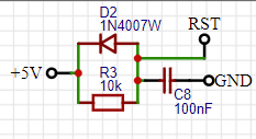
While some sort of cap is occasionally recommended there to delay startup when the power supply is "slowly rising", it shouldn't be necessary on a modern AVR (with brown-out detector), and I'm pretty sure it will interfere with the Arduino "auto-reset" circuit.
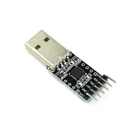
Also: what Serial adapter are you using? 5 pins is a bit uncommon. Are you sure it is connected correctly?
They do not add a capasitor from RST to GND(the one that you recommended to get rid of), and they add a resistor from DRT to GND, and that is the thing that I do not have, and I don't actually understand its purpose. What do you think about that?
Yeah, as far as I understand, I made a mistake when I didnt connect DTR to GND. They also do that in Arduino Uno, but I didn't get why is it done. As far as I understand I need to make +5V from the other side of capasitor(DTR), so it is +5V on both sides. I need to connect DTR of my board to GND, but I do not understand why do I need to use a resistor for that, if anyone can explain me, I would be very glad! So if I connect DTR to GND, it should be a HIGH on DTR pin of my Serail adapter, so the capasitor will charge and there will be +5V on both sides, when the reset is needed DTR will become low and on the one side of capasitor it will be Low(DTR), while on the other side High(RST), so the capasitor will discharge from the RST side(somehow, somewhere, idk how) and it will be a Low on the RST so, it will reset, and then charge back. It should be something like this, it is hard for me to understand, but seems that there is some kind of logic in that. But I am still would be very glad if anyone will explain me, why do we need a 1k resistor from DTR to GND, instead of just connecting it without resistor. And what happens when DTR becomes LOW? I don't understand, where excatly does the charge of the capasitor from the side of RST goes.
Okey, found more detailes. If I got it right, we need a 1k resistor, so we dont get a a dead short. So we add a resistance, so less current flow. Got it now. The question about where does the charge from capasitor from the side of RST goes is still unsolved.
No resistor between DTR and GND is needed. DTR does not have to be connected directly or indirectly to GND. I can see the sense in adding a resistor between DTR and GND to protect against some kind of spurious input if someone touches a finger to an unconnected DTR line if no UART bridge is connected or something like that. It's really not necessary.
Removing C8 from your circuit should make the auto-reset function work just fine. I've always done it that way. If you feel the need to add C8, I'd make sure it's a lot smaller than C6; use 10nF or so. But start by simply removing it.
Also, if you don't want/cannot remove C8, try shorting RST to GND manually during the start of the UART download process to see if this indeed does fix the issue. If it works with the manual reset, you know for sure the problem is indeed related to the RST pulse.
Then I just dont understand how removing C8 helps me. The biggest question then is why did I add that then, because there is no such capasitor in any scheme I saw.
I just tried manually(plaguied the wire into the GND and touched different places where RST is open(leg of microcontroller, capasitor, resistor) and it did not work.
Grounding DTR generates a pulse on the other side of C6, because a capacitor's series response to a step function is essentially differentiation. C8 does it's best to absorb that pulse, because a cap to ground is an integrator. Since they're of equal value, I'd guess that the amplitude of the resulting RESET pulse is about half what it ought to be. Essentially you have a voltage divider made of Caps, that works on pulses.
Did you get the timing right though? It needs to happen in the first few seconds of the download procedure.
Also check with a multimeter or preferably a scope that the RST pulse makes it through from UART DTR to the microcontroller.
If the manual RST didn't help, but the microcontroller as such is functioning and you can program it through SPI just fine, then verify whether the UART TX and RX do work and are properly connected. Can you output Serial.print to the serial monitor and does it show up OK with the FTDI adapter connected to the board? And can you successfully send data back to the microcontroller over UART as well? You can make a small echo sketch that simply echoes back on UART what it receives.