Hello guys,
i plan to use an atmega328q (tqfp32) to control some leds drivers IC.
Atmega will be mounted on a specific PCB. And will be not loaded with arduino bootloader.
As the analogWrite() page explain
The PWM outputs generated on pins 5 and 6 will have higher-than-expected duty cycles. This is because of interactions with the millis() and delay() functions, which share the same internal timer used to generate those PWM outputs. This will be noticed mostly on low duty-cycle settings (e.g. 0 - 10) and may result in a value of 0 not fully turning off the output on pins 5 and 6.
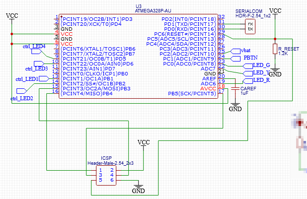
Is this possible to share the ICSP pins (atmega pin 13/14/15) to drive leds when device is on operational mode and use icsp on the early time to flash bootloader ?
See bellow picture for what i intend to do. Can someone gives me an advice about this
Given that you have the proper resistors - 220 Ohm or more - in series with your LEDs, the only requirement would seem to be that your ICSP programmer also uses an ATmega chip with the ability to drive those LEDs in the process of programming.
Doesn't your ICSP header have RESET, and power? Also you didn't show where the SPI lines go when they leave the portion of the diagram you cut out and pasted. It's important to know what they're connected to.
Hello,
Can someone confirm that there's nothing missing on this scheme to flash arduino bootloader (with either tinyISP or another arduino board). This device will be soldered on a PCB and I will not be able to change connection afterthat, that's why i'm a little concerned.
Note that i do not use external crystal and i plan to use the device with internal oscillator. VCC is a regulated voltage.
Doesn't your ICSP header have RESET, and power? Also you didn't show where the SPI lines go when they leave the portion of the diagram you cut out and pasted. It's important to know what they're connected to.
Not for now, i was thinking that is not mandatory (project is battery powered, and will be on while flashing and reset could be performed manually by powering off). If it is i'll add those right away.
I'm pretty sure the USBASP or equivalent has to hold the part in a reset state at some times during the upload process. So just power cycling your board probably won't work.
Anyway, can't you just look at every similar design and see that it has it? It's not food for thought?
Doesn't work that way with a LED.
PWM only controls the 'on' time of the LED, not the current.
LED current will be what you set with hardware, unless you unspecified driver is different.
ADC6 and ADC7 are analogue input only.
Can't be used to drive LEDs.
Leo..
I add this pullup resistor originally to not have reset pin floated and permanently connected to vcc. Was before your remark about ICSP reset pin connected to reset. I did not check this while posting back the screenshot.
I read the "serial downloading" chapter from atmel datasheet. Now i understand why reset pin on icsp is mandatory.
It answers another question about external component needed (specifically crystals) :
If the device is clocked by the internal oscillator, it is no need to connect a clock source to the XTAL1 pin.
So crystals are not mandatory (if fuses are correctly set).
And no, do not try to guess everything, but try to do my best and go find help sometime.
So thank you.