Attiny85 digispark to drive 12v motor using mosfet

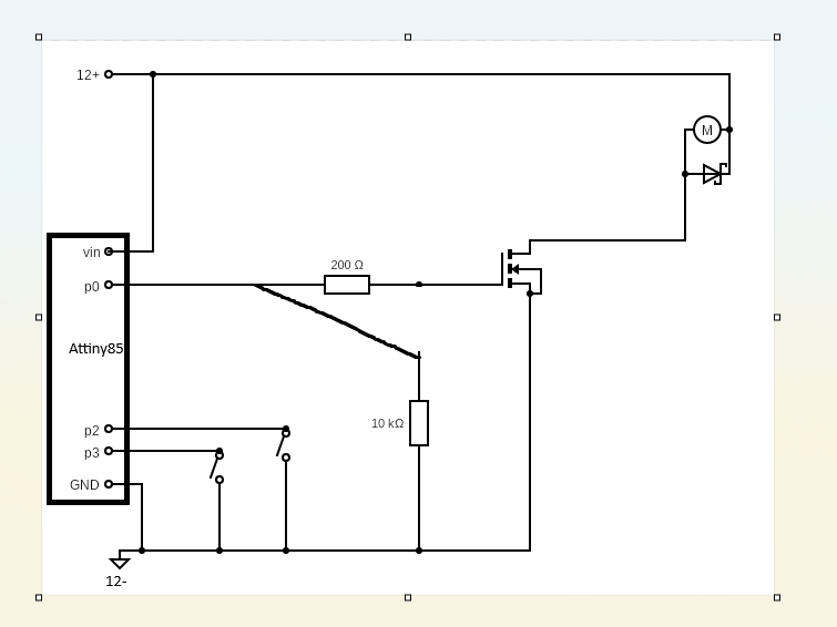
Hello all, I am trying to control a 12 v motor type JCY370 (12V, 0.5A load, 0.6A stall) using an attiny85 controller via two float switches. When switch one is in high position, the motor need to turn for one minute and then there needs to be a timeout of one hour before it can run again. The second float switch acts as a safety; the motor cannot run if this switch is in high position.

Other components used:
RFP30N06LE MOSFET
SB560 Diode
0.1µF ceramic capacitor for decoupling

schematic:

Code:

const int FLOAT_SWITCH_1 = 2; // PB2, Pin 7

const int FLOAT_SWITCH_2 = 3; // PB3, Pin 2

const int MOTOR_PIN = 0; // PB0, Pin 5


const unsigned long RUN_TIME = 10000; // 10 seconds

const unsigned long TIMEOUT = 3600000UL; // 1 hour


unsigned long lastRunTime = 0;

bool motorRunning = false;

unsigned long motorStartTime = 0;


void setup() {

pinMode(FLOAT_SWITCH_1, INPUT_PULLUP);

pinMode(FLOAT_SWITCH_2, INPUT_PULLUP);

pinMode(MOTOR_PIN, OUTPUT);

digitalWrite(MOTOR_PIN, LOW);

}


void loop() {

bool float1High = (digitalRead(FLOAT_SWITCH_1) == HIGH); 

bool float2High = (digitalRead(FLOAT_SWITCH_2) == HIGH); 

unsigned long currentTime = millis();


if (motorRunning) {

if (currentTime - motorStartTime >= RUN_TIME) {

digitalWrite(MOTOR_PIN, LOW);

motorRunning = false;

lastRunTime = currentTime;

}

}

else if (float1High && !float2High && (currentTime - lastRunTime >= TIMEOUT)) {

digitalWrite(MOTOR_PIN, HIGH);

motorRunning = true;

motorStartTime = currentTime;

}

}

But this does not seem to work. Any advice as to what I'm missing?

What's the VIN here?

Move the upper point of the 10k resistor to p0.

the digispark attiny85 can receive up to 12v as input

I didn't catch it from title, my bad.

like this? the 10k resistor is supposed to pull the gate down when the P0 is low.

Did you wait an hour after powering it on so that currentTime - lastRunTime >= TIMEOUT would be true? Because it appears at first glance that you can't start the motor up until an hour after the ATtiny85 starts.

Perhaps try initializing unsigned long lastRunTime = -TIMEOUT; if you want to be able to start the motor up within the first hour of powering up the ATtiny85.

  • BTW, let the compiler do the heavy lifting :wink:
const unsigned long TIMEOUT = 3600000UL; // 1 hour

Verses

const unsigned long TIMEOUT = 60 * 60 * 1000UL; // 1 hour

The best way is to pull down the controller output! There's were the capacitor is, not at the gate!

That is a great catch! I'll try it out and will report back.

Hello @LarryD, I'm not sure what you mean? Is your second option better? Why exactly? Thanks!

const unsigned long TIMEOUT = 60 * 60 * 1000UL; // 1 hour

  • it’s all about documenting your sketches

  • 3600000 milliseconds six months from now this is a meaningless number.
    60 * 60 * 1000 milliseconds reminds you (hopefully) 60 min in one hour 60 seconds in minute.

  • Better still, this is often use:

#define ONE_SECOND   1000ul              // ms
#define ONE_MINUTE   (ONE_SECOND * 60ul) // 60 seconds in one minute 
#define ONE_HOUR     (ONE_MINUTE * 60ul) // 60 minutes in one hour
#define ONE_DAY      (ONE_HOUR * 24ul)   // 24 hours in one day 
  • in your code you can write . . .
unsigned long TIMEOUT = ONE_HOUR;  // 1 hour
. . .
unsigned long TIMEOUT = 30ul * ONE_MINUTE  // 30 minutes
. . .
unsigned long TIMEOUT = 2ul * ONE_HOUR + 23ul * ONE_SECOND;   // two hours and 23 seconds

Repeat, it’s all about documenting

Thanks all, I managed to get it working using my original shematic and the following code.

const int FLOAT_SWITCH_1 = 2; // PB2, Pin 7
const int FLOAT_SWITCH_2 = 3; // PB3, Pin 2
const int MOTOR_PIN = 0; // PB0, Pin 5

#define ONE_SECOND   1000UL              // ms
#define ONE_MINUTE   (ONE_SECOND * 60UL) // 60 seconds in one minute 
#define ONE_HOUR     (ONE_MINUTE * 60UL) // 60 minutes in one hour
#define ONE_DAY      (ONE_HOUR * 24UL)   // 24 hours in one day 

const unsigned long RUN_TIME = 10 * ONE_SECOND; // 10 seconds
const unsigned long TIMEOUT = ONE_HOUR; // 1 hour


unsigned long lastRunTime = -TIMEOUT;
bool motorRunning = false;
unsigned long motorStartTime = 0;


void setup() {
pinMode(FLOAT_SWITCH_1, INPUT_PULLUP);
pinMode(FLOAT_SWITCH_2, INPUT_PULLUP);
pinMode(MOTOR_PIN, OUTPUT);
digitalWrite(MOTOR_PIN, LOW);
}


void loop() {
bool float1High = !(digitalRead(FLOAT_SWITCH_1) == HIGH); 
bool float2High = !(digitalRead(FLOAT_SWITCH_2) == HIGH); 
unsigned long currentTime = millis();
if (motorRunning) {
if ((currentTime - motorStartTime) >= RUN_TIME) {
digitalWrite(MOTOR_PIN, LOW);
motorRunning = false;
lastRunTime = currentTime;
}
}
else if (float1High && !float2High && (currentTime - lastRunTime >= TIMEOUT)) {
digitalWrite(MOTOR_PIN, HIGH);
motorRunning = true;
motorStartTime = currentTime;
}
}

Only now, I did not use a 0.1µF ceramic capacitor for decoupling on the digispark Attiny85 between Vin and Gnd. Is it neccesary to include it?

  • Decoupling is absolutely necessary.

  • Not using decoupling leaves you open to intermittent problems that will make you pull out your hair.

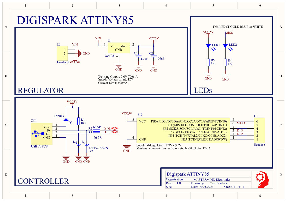
if I look up the shematic for the digispark attiny85 I'm using, I see some capacitors on the 5v to GND lines, but I'm powering it using the same 12v as for the motor. Is it then still usefull to add a 0.1 µF between the VIN and the GND?